4.3.6. Cylinder operator
The Cylinder operator, shown in Figure 4.24, slices a dataset with a cylinder whose size and orientation are specified by the user. The result is a cylindrical surface.
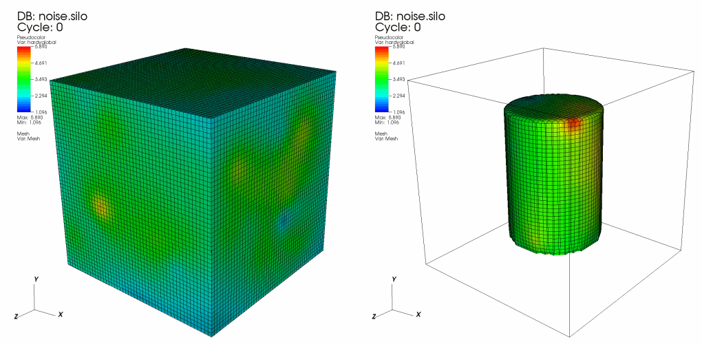
Fig. 4.24 Cylinder operator example: original plot; plot clipped by cylinder
4.3.6.1. Setting the cylinder’s endpoints
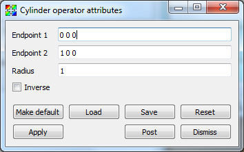
There are two ways to set the endpoints for the Cylinder operator. First of all, you can open the Cylinder operator window (see Figure 4.25) and type new 3D points into the Endpoint 1 and Endpoint 2 text fields. The second, and more interactive way to set the endpoints for the Cylinder operator is to use VisIt’s interactive Line tool, which is discussed in the Interactive Tools chapter. The Line tool lets you interactively place the Cylinder operator’s endpoints anywhere in the visualization. The Line tool’s endpoints correspond to the centers of the cylinder’s top and bottom circular faces.