10. Creating a Database reader plugin
This section shows how to extend VisIt by writing a new database reader plugin so you can use VisIt to access data files that you have already generated. Writing a database reader plugin has several advantages over other approaches to importing data into VisIt such as writing a conversion program. First of all, if VisIt can natively read your file format then there is no need to convert files and consume extra disk space. Converting files may not even be possible if the data files are prohibitively large. Secondly, plugins offer the advantage of not having to alter a complex simulation code to write out data that VisIt can read. New plugins are free to read the simulation code’s native file format. While many approaches to importing data into VisIt require new specialized code, when you write a database plugin, the code that you write is external to your simulation and it is not a converter that you have to maintain. There is no doubt that there is some maintenance involved in writing a database reader plugin for VisIt but there is always the option of contributing your plugin back into the VisIt source code tree where the code maintenance burden is shared among the developer community.
10.1. Structure of VisIt
VisIt is a parallel, distributed application that consists of four component processes that work in tandem to produce your visualizations. The two components that you may already be familiar with are the client and the viewer. VisIt has GUI, Python interface, and Java clients that control the visualization operations performed by the viewer, which is the central state repository and graphics rendering component. The other components, which are not immediately visible, are the database server and the compute engine. The database server (sometimes called the metadata server) is responsible for browsing the file system and letting you know which files can be opened. Once you decide on a file to open, the database server attempts to open that file, loading an appropriate database reader plugin to do so. Once the database server has opened a file, it sends file metadata such as the list of available variables to the client and the viewer. The compute engine comes into play when you want to create a plot to process your data into a form that can be rendered on the screen. The compute engine, like the database server, loads a plugin to read a data file and does the actual work of reading the problem-sized data from the file and translating it into Visualization Toolkit (VTK) objects that VisIt can process. Once the data has been read, it is fed through the visualization pipeline and returned to the viewer component where it can be displayed.
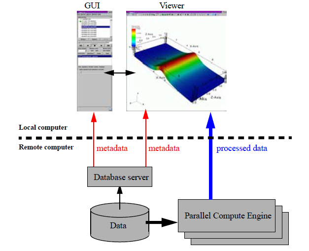
Fig. 10.28 VisIt’s architecture
10.1.1. Plugins
VisIt supports three types of plugins: plot plugins, operator plugins, and database reader plugins. This chapter explores database reader plugins as a method of importing data from new file formats into VisIt. A database reader plugin is made of three shared libraries, which are dynamically loaded by the appropriate VisIt components when data from a file must be read. The VisIt components involved in reading data from a file are the database server and the compute engine. Each database reader plugin has a database server component, a compute engine component, and an independent component, for a total of three shared libraries (libM, libE, libI).
The independent plugin component, or libI plugin component, is a very lightweight shared library containing little more than the name and version of a plugin as well as the file extensions that should be associated with it. When the database server and compute engine initialize at runtime, one of their first actions is to scan VisIt’s plugin directories for available libI plugins and then load all of the libI plugins to assemble an internal list of known plugins along with the table of file extensions for each file.
When VisIt needs to open a file, the filename is first passed to the database server, which tries to extract a file extension from the end of the filename so an appropriate plugin can be selected from the list of available plugins. Once one or more matches are made, the database factory object in the database server loads the libM plugin component for the first plugin in the list of matching plugins. The libM plugin component is the piece of the plugin used by the database server and it is used to read the metadata from the file in question. If the plugin cannot open the file then it should throw an exception to make the database factory attempt to open the file using the next matching plugin. If there are no plugins that match the file’s file extension then a default database plugin is used. If that plugin cannot open the file then VisIt issues an error message. Once the libM plugin has read the metadata from the file, that information is sent to the VisIt clients where it can be used to populate variable menus, etc.
When you add a plot in VisIt and click the Draw button, the first step that the compute engine takes to process your request is to open the file that contains the data. The procedure for opening the file that contains the data in the compute engine is the same as that for the database server. In fact, the same database factory code is used internally. However, the database factory in the compute engine loads the libE plugin component. The libE and libM plugin components are essentially the same except that, when possible, database server plugin components do less work. Both the libE and libM plugin components contain code to read a file’s metadata and both contain code to read variables and create meshes. The difference between the two plugin types is that the code to read the variables and create meshes is only called from the libE plugin component.
10.2. Picking a database reader plugin interface
Database reader plugins have 4 possible interfaces, which affect how files are mapped to plugin file format objects. The 4 possible interfaces are shown in the table below:
SD |
MD |
|
|---|---|---|
ST |
STSD - Single timestate per file and it contains just 1 domain. |
STMD - Single timestate per file but each file contains multiple domains. |
MT |
MTSD - Multiple timestates per file and each file contains just 1 domain. |
MTMD - Multiple timestates per file and each file contains multiple domains. |
In order to pick which plugin interface is most appropriate for your particular file format, you must consider how your file format treats time and domains. If your file format contains multiple timestates in each file then you have an MT file format; otherwise you have an ST file format. If your file format comes from a parallel simulation then you will often have some type of domain decomposition, which breaks up the entire simulation into smaller pieces called domains that are divided among processors. If your simulation has domains and the domains are written to a single file then you have an MD file format; otherwise, if your simulation processors wrote out their own files then you have an SD file format. When you consider both how your file format deals with time and how it deals with domains, you should be able to select which plugin interface you will need when you write your database reader plugin.
10.3. Using XMLEdit
Once you pick which database interface you will use to write your database plugin, the next step is to use VisIt’s XMLEdit tool to get started with some interface definitions. XMLEdit is a graphical application that lets you create an XML file that describes some of the basic attributes for your database reader plugin. The XML file contains information such as the name of the plugin, its version, which interface is used, the plugin’s list of file extensions, and any additional libraries or source code files that need to be included in the plugin in order to build it.
To get started with building your plugin, the first step is to create a source code directory to contain all of the files that will be created to generate your plugin.
It is best that the directory name be the name of your file format or the name of your simulation.
Once you have created a directory for your plugin files, you can run VisIt’s XMLEdit program.
To start XMLEdit on UNIX systems where VisIt is installed, open a command window and type xmledit.
On Windows systems, XMLEdit should be available in the Start menu under VisIt’s plugin development options.
Or, run from a command prompt: C:\path\to\visit\xmledit, substituting the correct path to the location where VisIt is installed.
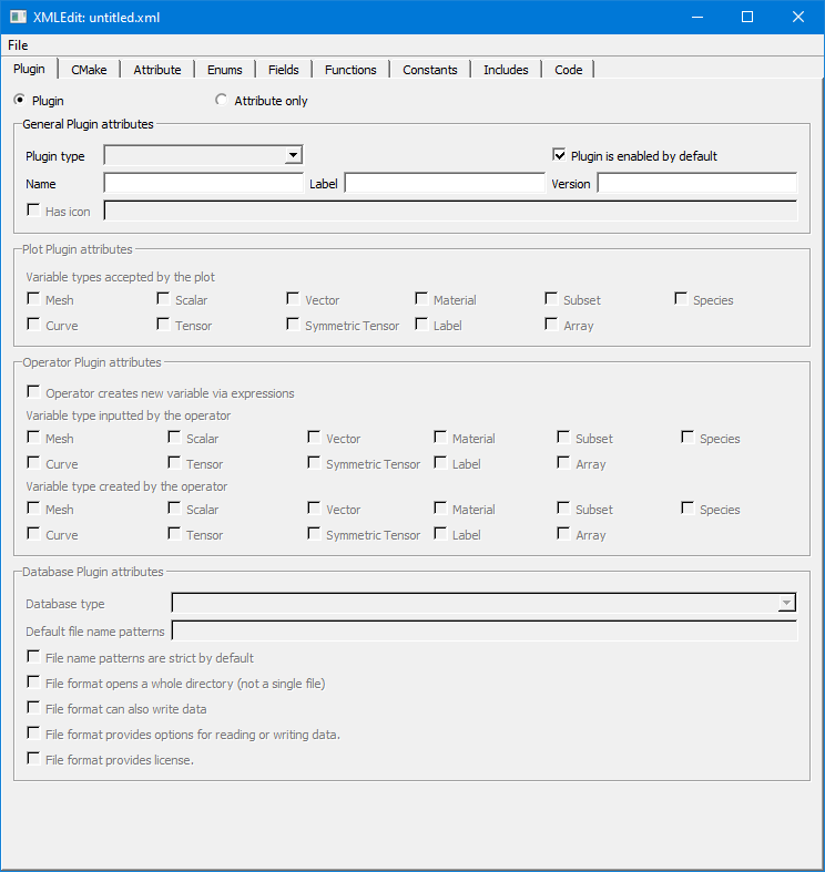
Fig. 10.29 XMLEdit plugin tab
Once XMLEdit is active you can see that it has a number of tabs that are devoted to various aspects of plugin development. Most of the tabs are used for developing plot and operator plugins only so this section will focus on the actions that you need to take to create your database reader plugin. First of all, you must type the name of your plugin into the Name text field. The name should match the name of the source code directory that you created - be sure that you pick a name that can be used inside of C++ class names since the name is used to help generate the plugin code skeleton that will form the basis of your database reader plugin. Next, type in a label into the Label text field. The label for a database plugin can contain a longer identifier that will be displayed when VisIt uses your plugin to read files. The label may contain spaces and punctuation. Next, enter the version of your plugin into the Version text field. The version for initial development should be 1.0. Now, choose Database from the Plugin type combo box to tell XMLEdit that you want to build a database reader plugin. Once you choose Database for your plugin type, some additional options will become enabled. You can ignore these options for now since they contain reasonable default values.
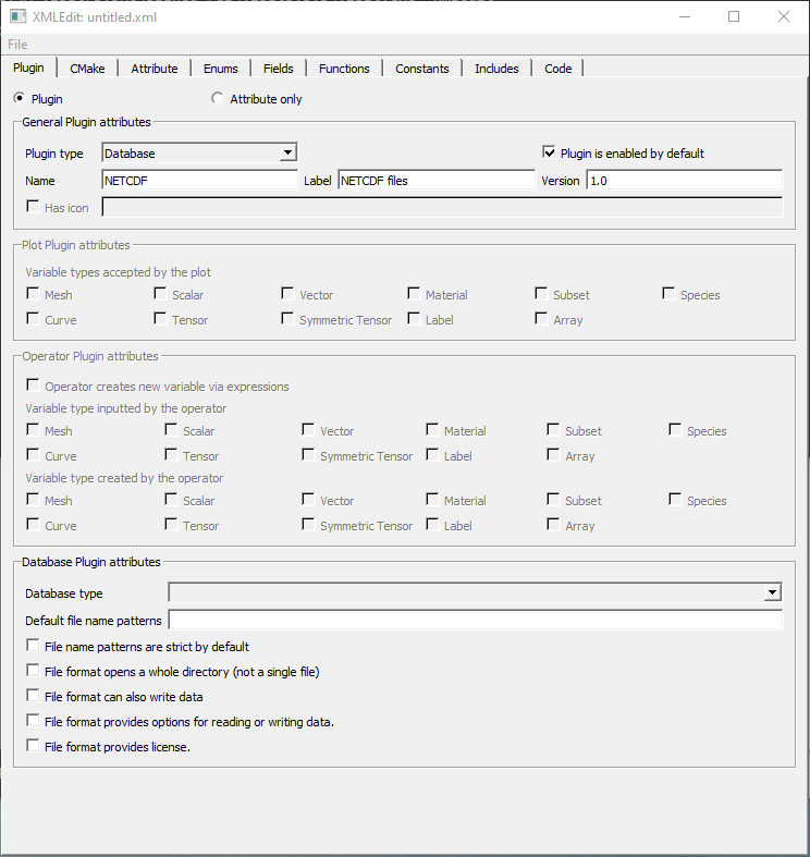
Fig. 10.30 XMLEdit plugin tab after filling in General Plugin Attributes
The next step in creating your database plugin using XMLEdit is to set the database type to either STSD, STMD, MTSD, or MTMD by selecting one of those options from the Database type combo box. Note that it is possible to instead choose to create a fully custom database type but do not choose that option since most formats do not need that level of customizability. Once you have selected a database type for your plugin, type in the list of file formats that you want to associate with your plugin. You can enter as many space-delimited file extensions as you want.
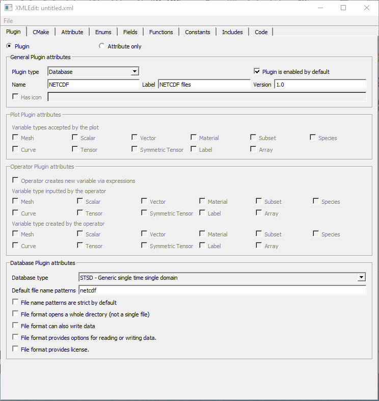
Fig. 10.31 XMLEdit plugin tab after choosing Database Type and filling in Default file name patterns
The information that you entered is the minimum amount of information required to create your database reader plugin. Save your XMLEdit session to an XML file by selecting Save from the File menu. Be sure to use the same name as you used for the directory name that will contain your plugin files and also be sure to save your XML file to that directory. At this point, you can skip ahead to generating your plugin code skeleton or you can continue adding options to your XML file.
10.3.1. CMake options
VisIt uses CMake for its build system and for the build systems of its plugins. XMLEdit contains controls on its CMake tab that allow you to add options to your XML file that will influence how your plugin code is built when you go to compile it. For example, the CMake tab includes options that allow you to specify compiler options such as CXXFLAGS, LDFLAGS and LIBS.
Adding options to these fields can be particularly useful if your plugin uses an external library such as NetCDF or HDF5. If you are using a library that VisIt provides (NetCDF, HDF5, CGNS, Silo, etc.) then you can use special predefined CMake variables that VisIt’s build defines to locate those libraries. For example, you could use ${NETCDF_INCLUDE_DIR}, ${NETCDF_LIBRARY_DIR}, ${NETCDF_LIB} to reference the include directory, library directory, and library name for the NetCDF library. Just substitute another capitalized library name for NetCDF to use variables for other I/O libraries. It is better to use these CMake variables for libraries that VisIt provides to ensure that your plugin is linked against the right libraries.
If you are using a library that VisIt does not support, you can add the include file and library file locations to ensure that the compiler will know where to look for your external library when your plugin is built.
Be sure to use -I/path/to/include in the CXXFLAGS when you want to add include directories for your plugin.
Use -L/path/to/lib in the LDFLAGS when you want to add link directories for your plugin.
Finally, add the name of the library (e.g. netcdf instead of -lnetcdf) in the LIBS when you need to link against additional libraries.
LIBS may contain the full-path to a library, in which case use of LDFLAGS to locate the library is unnecessary.
You can also add extra files to the libE and libM plugins by adding a list of files to the Engine files and MDServer files text fields, respectively. There are also rarely needed MDServer-specific or Engine-specific defines, cxxflags, or ldflags. The engine options are further broken down into serial and parallel versions.
If you change any of these options, shown in Figure 10.32, be sure to save your XML file before quitting XMLEdit.
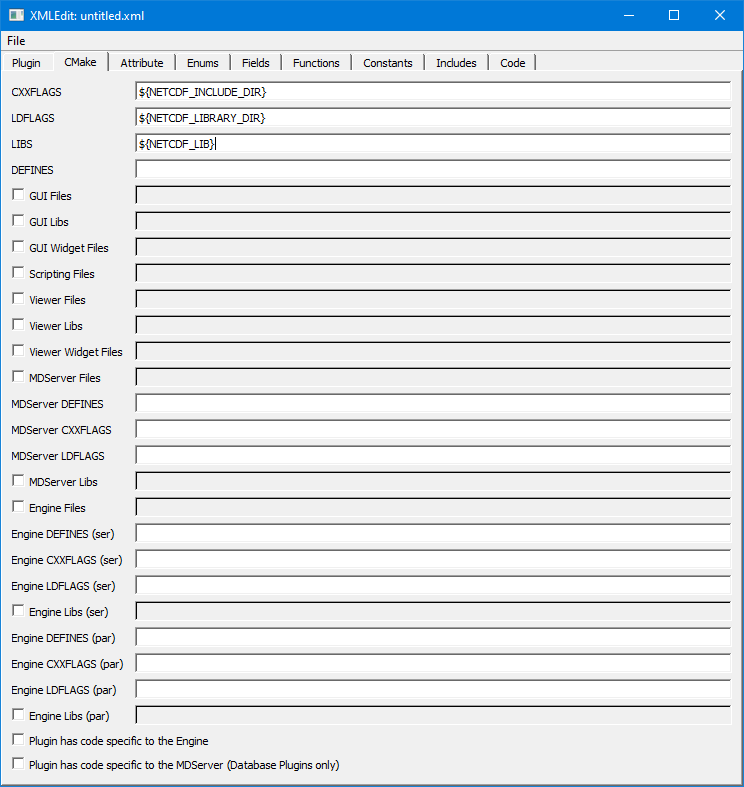
Fig. 10.32 XMLEdit CMake tab
10.4. Generating a plugin code skeleton
Once you save your work from XMLEdit, you will find an XML file containing the options that you provided in the directory where you store your plugin files.
VisIt provides more XML tools to generate the necessary code skeleton for your plugin.
The important tools when building a database plugin are: xml2cmake, xml2info and xml2plugin.
The xml2plugin program is actually a script that automates calling the required xml2* programs.
In order to generate your plugin code skeleton, open a command window, go to the directory containing your XML file, and run xml2plugin.
The command that you will run is:
xml2plugin -clobber FILE.xml
Be sure to replace FILE.xml with the name of your own XML file.
Once you run the xml2plugin program, if you look in your directory, you will see several new files.
You can also generate the plugin skeleton code from XMLEdit by Choosing Generate code from the File menu. You can check all the options, the ones that don’t apply to database plugins (C++, Java, Python, Window) will be ignored.
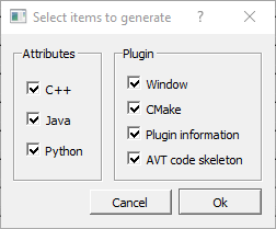
Fig. 10.33 Generate code options
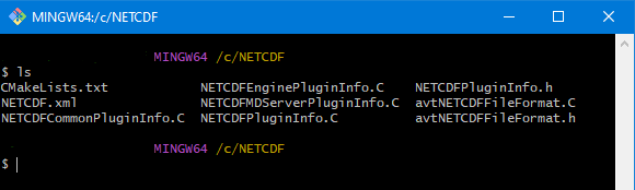
Fig. 10.34 Listing of files after running xml2plugin.
For database reader plugins, there are essentially three classes of files that xml2plugin creates.
First of all, xml2plugin creates the plugin code skeleton, which includes the plugin entry points that are used to load the plugin dynamically at runtime.
These files have Info in their name and they are generated by the xml2info program.
If you change the name, version, or file extensions that your plugin uses then you should re-run xml2info instead of running xml2plugin.
The next set of files are the AVT file format source and header files.
The AVT file format source code files are C++ source code files that you will complete using new code to read your file format.
Finally, xml2cmake created a CMakeLists.txt file that CMake can use to generate a build system for your plugin.
If you run cmake . at the command prompt and you are on a UNIX system such as Linux or macOS, CMake will generate a Makefile for your plugin.
In that case, all you have to do in order to build your plugin is type: make at the command prompt.
10.5. Building your plugin
So far, we have created an XML file using the XMLEdit program and then used the XML file with VisIt’s XML tools to generate plugin source code. The static portions of the generated source code are complete but there are still some pieces that you need to write yourself in order to make VisIt read your data files. The automatically generated files that are called avtXXXXFileFormat.C and avtXXXXFileFormat.h, where XXXX is the name of your plugin, are incomplete. These two AVT files contain a derived class of one of the STSD, STMD, MTSD, MTMD file format classes that VisIt provides for reading different file types. Your job is to fill in the missing code in the methods for the AVT classes so they can read data from your file format and translate that data into VTK objects. By default, the AVT files contain some messages in the source code like YOU MUST IMPLEMENT THIS, which are meant to prevent the source code from compiling and to call attention to areas of the plugin that you need to implement. An example of this message is shown in Figure 10.35.
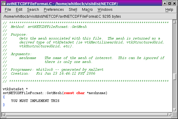
Fig. 10.35 IMPLEMENT THIS message
The first step in building a plugin is to make sure that the automatically generated source code compiles.
Open the AVT files and look for instances of the YOU MUST IMPLEMENT THIS message and, when you find them, write down a note of where they appear.
Comment out each of the messages in the C++ source code and add return 0; statements (See Figure 10.36).
By commenting out the offending messages, the automatically generated source code will compile when you attempt to compile the plugin.
You will also have a list of some of the plugin methods that you will have to write later when you really begin developing your plugin.
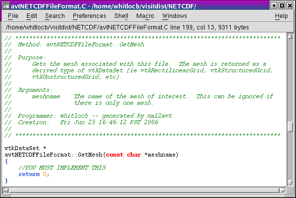
Fig. 10.36 Commented-out IMPLEMENT THIS message
Once you have changed the AVT files so there are no stray messages about implementing a plugin feature, go back to your command terminal and type cmake -DCMAKE_BUILD_TYPE:STRING=Debug so CMake will generate a build system for your plugin.
The generated build system is most commonly a Makefile, allowing you to use the make command for your system.
The make command takes the automatically generated Makefile that was generated by CMake and starts building your plugin against the installed version of VisIt.
For Windows OS and Visual Studio, you will need to tell CMake which generator and toolset to use, and should be the same as that used to compile VisIt itself. The cmake-gui makes this easy. See Configuring With CMake GUI for more information. Your entry for Where is the source code will be the same directory as your .xml file. You entry for Where to build the binaries can be the same as source, but choosing a separate build folder is the better option, as it won’t clutter your source folder with build files.
If you encounter compilation errors, such as syntax errors, then you most likely need to make further changes to your AVT files before trying to build your plugin.
A good C++ language reference can help you understand the types of errors that may be printed to your command window in the event that you have not successfully changed the AVT files.
If your source code seems to compile but fails due to missing libraries such as NetCDF or HDF5 then you can edit your XML file so it points to the right library installation locations.
Note that if you edit your XML file, you will need to regenerate the CMakeLists.txt file using xml2cmake.
It is also a good idea that you remove the CMakeCache.txt file before rerunning cmake if you have changed the path to any libraries in your XML file.
Once your plugin is built, it will be stored in a platform-specific subdirectory of the .visit directory in your home directory (~/.visit).
If you type: find ~/.visit -name "*.so" into your command window, you will be able to locate the libE, libI, and libM files that make up your compiled plugin (see Figure 10.37).
If you develop for macOS, you should substitute *.dylib for *.so in the previous command because shared libraries on macOS have a .dylib file extension instead of a .so file extension.
If you develop on Windows, the files will be in your profile directory (generally C:\users\<yourname>) in a VisIt folder. The file extension is .dll.
Note that when a parallel compute engine is available in the installed version of VisIt, you will get two libE plugins; one with a _ser suffix and one with a _par suffix. The libE files that have a _ser suffix are loaded by the serial compute engine and the _par libE file is loaded by the parallel compute engine and may contain parallel function calls, such as calls to the MPI library.
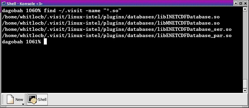
Fig. 10.37 Plugin build results
When VisIt’s database server and compute engine execute, they look in your ~/.visit directory for available plugins and load any that are available. This means that even if you build plugins against the installed version of VisIt, it will still be able to find your private plugins.
It is recommended that while you develop your plugins, you only install them in your ~/.visit directory so other VisIt users will not be affected.
However, if you develop your plugin on macOS, you will have to make sure that your plugins are installed publicly so that they can be loaded at runtime.
You can also choose to install your plugins publicly once you have completed development.
To install plugins publicly, first remove the files that were installed to your ~/.visit directory by typing the make clean command in your command window.
Next, re-run the xml2cmake program like this:
xml2cmake -public -clobber FILE.xml
Adding the -public argument on the command line causes make to install your plugin files publicly so all VisIt users can access them.
Don’t forget to rerun cmake and make after running xml2cmake.
10.6. Calling your plugin for the first time
Once you have completed building your plugin for the first time, all that you need to do is run VisIt and try to open one of your files. When you open one of your files, the database server should match the file extension of the file that you tried to open with the list of file extensions that your plugin accepts, causing your plugin to be loaded and used for opening the file. You can verify that VisIt used your plugin by opening the File Information window (see Figure 10.38) in the VisIt GUI and looking for the name of your plugin in the listed information.
If your plugin wasn’t used by VisIt, it may mean that other formats can read the same extensions as your plugin. In that case, you would need to select your plugin from the Open file as type: dropdown option in the File open window to make VisIt choose your plugin.
Note that at this stage, the database server should be properly loading your database reader plugin but since no code to actually read your files has yet been added to the AVT source code files, no plottable meshes or variables will be available.
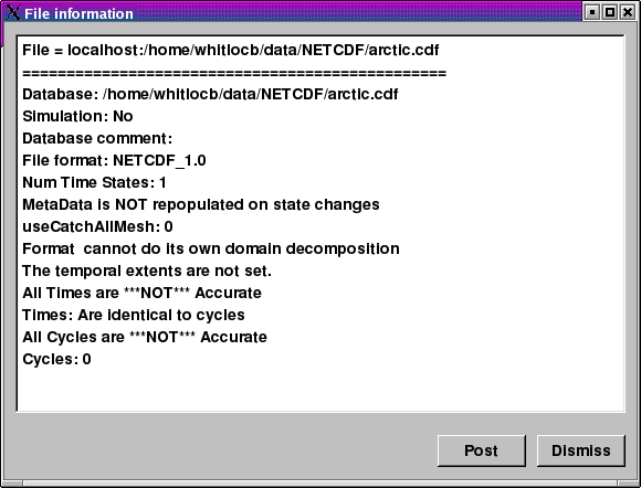
Fig. 10.38 File information window
10.7. Implementing your plugin
Now that you have built a working plugin framework, you are ready to begin adding code to your plugin that will make it capable of opening your file format, reading data, and translating that data into VTK objects. This section explores the details of writing the AVT code for your database reader plugin, providing necessary background and then diving into specific topics such as how to return data for a particular mesh type. Before starting, remember that building a plugin is an incremental process and you should proceed in small steps, saving your work, building, and testing your plugin each step of the way.
10.7.1. Required plugin methods
Most of the code in a VisIt database plugin is automatically generated and, for the most part, the only code that you need to modify is the AVT code. The AVT code contains a class definition and implementation for a derived type of the STSD, STMD, MTSD, or MTMD file format classes and your job as a plugin developer is to write the required methods for your derived file format class so that VisIt can read your file. There are many methods in the file format class interface that you can override to make your plugin perform specialized operations. The only methods that you absolutely must implement are:
- PopulateDatabaseMetaData
VisIt calls the PopulateDatabaseMetaData method when file metadata is needed. File metadata is returned in a pass-by-reference avtDatabaseMetaData object. File metadata consists of the list of names of meshes, scalar variables, vector variables, tensor variables, label variables, array variables, expressions, cycles, and times contained in the file. These lists of variables and meshes let VisIt know the names of the objects that can be plotted from your file. The metadata is used primarily to populate the plot menus in the GUI and viewer components. The PopulateDatabaseMetaData method is called by both the libM and libE plugins.
- GetMesh
VisIt calls the GetMesh method in a libE plugin when it needs to plot a mesh. This method is the first method to return “problem-sized” data, meaning that the mesh data can be as large as the data in your file. The GetMesh method must return a mesh object in the form of one of the VTK dataset objects (vtkRectilinearGrid, vtkStructuredGrid, vtkUnstructuredGrid, vtkPolyData).
- GetVar
VisIt calls the GetVar method in a libE plugin when it needs to read a scalar variable. Like the GetMesh method, this method returns “problem-sized” data. GetVar reads data values from the file format, possibly performing calculations to alter the data, and stores the data into a derived type vtkDataArray object such as vtkFloatArray or vtkDoubleArray. If your file format does not need to return scalar data then you can leave the
return 0;implementation that you added in order to get your plugin to build.- GetVectorVar
VisIt calls the GetVectorVar method in a libE plugin when it needs to read a vector or tensor variable. GetVectorVar performs the same function as GetVar but returns vtkFloatArray or vtkDoubleArray objects that have more than one value per tuple. A tuple is the equivalent of a value associated with a zone or node but it can store more than one value. If your file format does not need to return vector data then you can leave the
return 0;implementation that you added in order to get your plugin to build.
10.7.2. Debugging your plugin
Before beginning to write code for your plugin, you should know a few techniques for debugging your plugin since debugging VisIt can be tricky because of its distributed architecture. See Debugging Tips for detailed information.
10.7.3. Opening your file
When VisIt receives a list of files to open, it tries to determine which plugin should be loaded to access the data in those files. The match is performed by comparing the file extension of the files against the known file extensions or patterns for all database reader plugins. Each plugin in the list of matches is loaded and VisIt creates instances of the plugin’s AVT file format classes that are then used to access the data in the files. If the plugin’s file format classes can be successfully constructed then VisIt tries to get the file’s metadata. It is very important that your file format’s constructor do as little work as possible, and try at all costs to avoid opening the files. Remember, VisIt could be creating a long list of your file format objects and opening the file in the constructor will really slow down the process of opening a file. It is better to instead add a boolean initialized member to your class and an Initialize method that reads the file to check its contents. Then override the ActivateTimestep method for your file format class and call your Initialize method from it. We make Initialize its own method so we can call it from other methods such as GetMesh or GetVar just in case.
In the event that your Initialize method cannot open the file if the file is not the right type, or if it contains errors, or if it cannot be accessed for some other reason, the constructor must throw an InvalidDBTypeException exception. When the InvalidDBTypeException exception is thrown, VisIt’s database factory catches the exception and then tries to open the file with the next matching plugin. This procedure ccontinues until the file is opened by a suitable plugin or the file cannot be opened at all.
Example for identifying a file.
// NOTE - This code is incomplete and is for example purposes only.

#include <InvalidDBTypeException.h>

avtXXXXFileFormat::avtXXXXFileFormat(const char *filename)
      : avtSTSDFileFormat(filename)
{
    initialized = false;
}
// Override this method in your reader
void
avtXXXXFileFormat::ActivateTimestep()
{
    Initialize();
}
// Provide this method in your reader
void
avtXXXXFileFormat::Initialize())
{
    if(!initialized)
    {
        bool okay = false;
        // Open the file specified by the filename argument here using
        // your file format API. See if the file has the right things in
        // it. If so, set okay to true.
        YOU MUST IMPLEMENT THIS
        // If your file format API could not open the file then throw
        // an exception.
        if (!okay)
        {
            EXCEPTION1(InvalidDBTypeException,
                       "The file could not be opened");
        }
        initialized = true;
    }
}
If your database reader plugin uses a unique file extension then you have the option of deferring any file opens until later when metadata is required. This is the preferred approach because VisIt may create many instances of your file format class and doing less work in the constructor makes opening files faster.
Once you decide whether your file format can defer opening a file or whether it must open the file in the constructor, you can begin adding code to your AVT class. Since opening files can be a costly operation, you might want to open a file and keep it open if you have a random access file format. If you open a file in one method and want to keep the file open so it is available to multiple plugin methods, you will need to add a new class member to your AVT class to contain the handle to your open file. If your file format consists of sequential text then you might consider reading the file once and keeping the data in memory in a format that you can conveniently translate into VTK objects. Both approaches require the addition of a new class member - either a handle to the file or a pointer to data that was read from the file.
10.7.4. Returning file metadata
Once your you have decided how your plugin will manage access to the file that it must read, the next step in writing your database reader plugin is to implement the PopulateDatabaseMetaData method. The PopulateDatabaseMetaData method is called by VisIt’s database infrastructure when information about a file’s meshes and variables must be obtained. The PopulateDatabaseMetaData method is usually called only the first time that a file format’s metadata is being read, though some time-varying formats can have time-varying metadata, which requires that PopulateDatabaseMetaData is called each time VisIt requests data for a new timestate. However, most file formats call PopulateDatabaseMetaData once.
The PopulateDatabaseMetaData method arguments can vary, depending on whether your file format is STSD, STMD, MTSD, or MTMD but in all cases the first argument is an avtDatabaseMetaData object. The avtDatabaseMetaData object is a class that is pervasively used in VisIt; it contains information about the files that you plot such as the number of domains, times, meshes, and variables that the files can provide. When you implement your plugin’s PopulateDatabaseMetaData method, you must populate the avtDatabaseMetaData object with the list of meshes and variables, etc. that you want VisIt to be able to plot. You can hard-code a fixed list of meshes and variables if your file format always contains the same entities or you can open your file and provide a dynamic list of meshes and variables. This section covers how to add meshes and various variable types to the avtDatabaseMetaData object so your file format’s data will be exposed in VisIt. For a complete listing of the avtDatabaseMetaData object’s methods, see the avtDatabaseMetaData.h header file. It is worth noting that the following code examples create metadata objects and manually add them to the metadata object instead of using convenience functions. This is done because the convenience functions used in automatically generated plugin code do not provide support for less often used metadata settings such as units and labels.
10.7.4.1. Returning mesh metadata
In order for you to be able to plot any data from your file format, your database reader plugin must add at least one mesh to the avtDatabaseMetaData object that is passed into the PopulateDatabaseMetaData method. Adding information about a mesh to the avtDatabaseMetaData object is done by creating an avtMeshMetaData object, populating its important members, and adding it to the avtDatabaseMetaData. At a minimum, each mesh must have a name, spatial dimension, topological dimension, and a mesh type. The mesh’s name is the identifier that will be displayed in VisIt’s plot menus and it is also the name that will be passed later on into the plugin’s GetMesh method.
The spatial dimension attribute corresponds to how many dimensions are needed to specify the coordinates for the points that make up your mesh. If your mesh exists in a 2D plane then choose 2, otherwise choose 3. Note that when you create the points for your mesh later in the GetMesh method, you will always create points that contain X,Y,Z points.
The topological dimension attribute describes the number of logical dimensions used by your mesh, regardless of the dimension of the space that it sits in. For example, you may have a planar surface of triangles sitting in 3D space. Such a mesh would be topologically 2D even though it sits in 3D space. The rule of thumb that VisIt follows is that if your mesh’s cells are points then you have a mesh that is topologically 0D, lines are 1D, surfaces are 2D, and volumes are 3D. This point is illustrated in Figure 10.39.
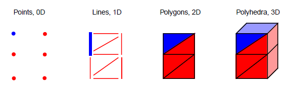
Fig. 10.39 Topological dimesnions. One zone is highlighted blue.
Once you have set the other basic attributes for your mesh object, consider which type of mesh you have. VisIt supports several different mesh types and the value that you provide in the metadata allows VisIt to tailor how it applies filters that process your data. If you have a mesh composed entirely of particles then choose AVT_POINT_MESH. If you have a structured mesh where the coordinates are specified by small vectors of values for each axis and the rest of the coordinates are implied then you probably have a rectilinear mesh and you should choose AVT_RECTILINEAR_MESH. If you have a structured mesh and every node has its own specific location in space then you probably have a curvilinear mesh and you should choose AVT_CURVILINEAR_MESH. If you have a mesh for which you specify a large list of nodes and then create cells using indices into that list of nodes then you probably have an unstructured mesh and you should choose AVT_UNSTRUCTURED_MESH for the mesh type. If you have a mesh that adaptively refines then choose AVT_AMR_MESH. Finally, if your mesh is specified using shapes such as cones and spheres that are unioned or differenced using boolean operations then you have a constructive solid geometry mesh and you should choose AVT_CSG_MESH for your mesh’s mesh type.
If your mesh consists of multiple domains then you will need to set the number of domains into the numBlocks member of the avtMeshMetaData object. Remember that the number of domains tells VisIt how many pieces make up your mesh and it is especially important to specify this number if your plugin is derived from an MD file format interface. You may also choose to tell VisIt what the domains are called for your file format. Some file formats use the word: “domains” while others use “brick” or “block”. If you choose to set the name that VisIt uses for domains then that term will be used in parts of VisIt’s GUI such as the Subset window. Set the blockPieceName member of the avtMeshMetaData object to a suitable term that describes a domain in the context of your simulation code. Alternatively, you can provide proper names by providing a vector of strings containing the names by setting the blockNames member.
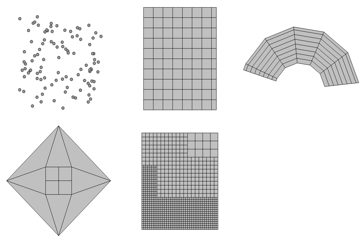
Fig. 10.40 AVT mesh types (AVT_CSG_MESH not pictured)
Now that the most important attributes of the avtMeshMetaData object have been specified, you can add extra information such as the names or units of the coordinate dimensions. Once all attributes are set to your satisfaction, you must add the avtMeshMetaData object to the avtDatabaseMetaData object.
Example for returning mesh metadata.
// NOTE - This code is incomplete and is for example purposes only.
void
avtXXXXFileFormat::PopulateDatabaseMetaData(avtDatabaseMetaData *md)
{
    // Add a point mesh to the metadata. Note that this example will
    // always expose a mesh called "particles" to VisIt. A real
    // plugin may want to read a list of meshes from the data
    // file.
    avtMeshMetaData *mmd = new avtMeshMetaData;
    mmd->name = "particles";
    mmd->spatialDimension = 3;
    mmd->topologicalDimension = 0;
    mmd->meshType = AVT_POINT_MESH;
    mmd->numBlocks = 1;
    md->Add(mmd);
    // Add other objects to the metadata object.
}
10.7.4.2. Returning scalar metadata
Once you have exposed a mesh to VisIt by adding mesh metadata to the avtDatabaseMetaData object, you can add scalar field metadata. A scalar field is a set of floating point values defined for all cells or nodes of a mesh. You can expose as many scalar variables as you want on any number of meshes. The list of scalar fields that a plugin exposes is often determined by the data file being processed. Like mesh metadata, scalar metadata requires a name so the scalar can be added to VisIt’s menus. The name that you choose is the same name that later is passed to the GetVar plugin method. Once you select a name for your scalar variable, you must indicate the name of the mesh on which the variable is defined by setting the meshName member of the avtScalarMetaData object. Once you have set the name and meshName members, you can set the centering member. The centering member of the avtScalarMetaData object can be set to AVT_NODECENT or AVT_ZONECENT, indicating that the data is defined on the nodes or at the zone centers, respectively. If you want to indicate units that are associated with the scalar variable, set the hasUnits member to true and set the units string to the appropriate unit names.
Example for returning scalar metadata.
// NOTE - This code is incomplete and is for example purposes only.
void
avtXXXXFileFormat::PopulateDatabaseMetaData(avtDatabaseMetaData *md)
{
    // Add a mesh called "mesh" to the metadata object.
    // Add a scalar to the metadata. Note that this plugin will
    // always expose a scalar called "temperature" to VisIt. A real
    // plugin may want to read a list of scalars from the data
    // file.
    avtScalarMetaData *smd = new avtScalarMetaData;
    smd->name = "temperature";
    smd->meshName = "mesh";
    smd->centering = AVT_ZONECENT;
    smd->hasUnits = true;
    smd->units = "Celsius";
    md->Add(smd);
    // Add other objects to the metadata object.
}
10.7.4.3. Returning vector metadata
The procedure for returning vector metadata is similar to that for returning scalar metadata. In fact, if you change the object type that you create from avtScalarMetaData to avtVectorMetaData then you are almost done. After you set the basic vector metadata attributes, you must set the varDim member to 2 if you have a 2-component vector or 3 if you have a 3-component vector.
Example for returning vector metadata.
// NOTE - This code is incomplete and is for example purposes only.
void
avtXXXXFileFormat::PopulateDatabaseMetaData(avtDatabaseMetaData *md)
{
    // Add a mesh called "mesh" to the metadata object.
    // Add a vector to the metadata. Note that this plugin will
    // always expose a vector called "velocity" to VisIt. A real
    // plugin may want to read a list of vectors from the data
    // file.
    avtVectorMetaData *vmd = new avtVectorMetaData;
    vmd->name = "velocity";
    vmd->meshName = "mesh";
    vmd->centering = AVT_ZONECENT;
    vmd->hasUnits = true;
    vmd->units = "m/s";
    vmd->varDim = 3;
    md->Add(vmd);
    // Add other objects to the metadata object.
}
10.7.4.4. Returning material metadata
Like the other types of mesh variables that we have seen so far, a material is defined on a specific mesh. However, unlike the other variables types, materials can be used to name regions of the mesh and can also be used by VisIt to break the mesh down into smaller pieces that can be turned on and off using the Subset window. Material metadata is stored in an avtMaterialMetaData object and it consists of: the name of the material object, the mesh on which it is defined, the number of materials, and the names of the materials. If you had a material called “mat1” defined on “mesh” and “mat1” was composed of: “Steel”, “Wood”, “Glue”, and “Air” then the metadata object needed to expose “mat1” to VisIt would look like the following code listing:
Example for material mesh metadata.
// NOTE - This code is incomplete and is for example purposes only.
void
avtXXXXFileFormat::PopulateDatabaseMetaData(avtDatabaseMetaData *md)
{
    // Add a mesh called "mesh" to the metadata object.
    // Add a material to the metadata. Note that this plugin will
    // always expose a material called "mat1" to VisIt. A real
    // plugin may want to use from the data file to construct
    // a material.
    avtMaterialMetaData *matmd = new avtMaterialMetaData;
    matmd->name = "mat1";
    matmd->meshName = "mesh";
    matmd->numMaterials = 4;
    matmd->materialNames.push_back("Steel");
    matmd->materialNames.push_back("Wood");
    matmd->materialNames.push_back("Glue");
    matmd->materialNames.push_back("Air");
    md->Add(matmd);
    // Add other objects to the metadata object.
}
10.7.4.5. Returning expressions
VisIt provides support for defining expressions to calculate new data based on the data in your file. VisIt provides the Expression window in the GUI for managing expression definitions. It can be convenient for users in certain fields, where custom expressions are used frequently, to store the expression definitions directly in the file format or to encode the custom expressions directly in the file metadata so they are always available when a given file is visualized. VisIt’s avtDatabaseMetaData object can contain custom expressions. Thus you can add custom expressions to the avtDatabaseMetaData object inside of your database reader plugin. Custom expressions are added to the avtDatabaseMetaData object by creating Expression (defined in Expression.h) objects and adding them by calling the avtDatabaseMetaData::AddExpression method. The Expression object lets you provide the name and definition of an expression as well as the expression’s expected return type (scalar, vector, tensor, etc.) and whether the expression should be hidden from the user. Hidden expressions can be useful if you build a complex expression that makes use of smaller sub-expressions that do not need to be exposed in the VisIt user interface.
Example for returning expression metadata.
// NOTE - This code is incomplete and is for example purposes only.
#include <Expression.h>

void
avtXXXXFileFormat::PopulateDatabaseMetaData(avtDatabaseMetaData *md)
{
    // Add a mesh called "mesh" to the metadata object.
    // Add scalars to the metadata object.
    // Add expression definitions to the metadata object.
    Expression *e0 = new Expression;
    e0->SetName("speed");
    e0->SetDefinition("{u,v,w}");
    e0->SetType(Expression::VectorMeshVar);
    e0->SetHidden(false);
    md->AddExpression(e0);
    Expression *e1 = new Expression;
    e1->SetName("density");
    e1->SetDefinition("mass/volume");
    e1->SetType(Expression::ScalarMeshVar);
    e1->SetHidden(false);
    md->AddExpression(e1);
    // Add other objects to the metadata object.
}
10.7.5. Returning a mesh
Once your database reader plugin can successfully return metadata about one or more meshes, you can proceed to implementing your plugin’s GetMesh method. When you make a plot in VisIt, the plot is set up using the file metadata returned by your plugin. When you click the Draw button in the VisIt GUI, it causes a series of requests that make the compute engine load your libE plugin and call its GetMesh method with the name of the mesh being used by the plot as well as the timestate and domain numbers (MT or MD formats only). A database reader plugin’s job is to read relevant data from a file format and translate the data into a VTK object that VisIt can process. The GetMesh method’s job is to read the mesh information from the file and create a VTK object that describes the mesh in the data file. VisIt can process many different mesh types (See Figure 10.40) and you can return different types of VTK objects that best describe your mesh type. This section gives example code to show how you would take data read from your file format and turn it into VTK objects that describe your mesh. The details of reading data from your file format are omitted from the example code listings because those details change for each file format. The central message in this section is how to use data from a file format to construct different mesh types.
10.7.5.1. Determining which mesh to return
The GetMesh method is always passed a string containing the name of the mesh that should be returned from the plugin. If your file format only ever has one mesh then you can ignore the meshname argument. However, if your file format can contain more than one mesh then you should check the name of the requested mesh before returning a VTK object so you create and return the correct mesh.
Example for which mesh to return in GetMesh
// NOTE - This code is incomplete and is for example purposes only.
#include <InvalidVariableException.h>
vtkDataSet *
avtXXXXFileFormat::GetMesh(const char *meshname)
{
    // Determine which mesh to return.
    if (strcmp(meshname, "mesh") == 0)
    {
        // Create a VTK object for "mesh"
        return mesh;
    }
    else if (strcmp(meshname, "mesh2") == 0)
    {
        // Create a VTK object for "mesh2"
        return mesh2;
    }
    else
    {
        // No mesh name that we recognize.
        EXCEPTION1(InvalidVariableException, meshname);
    }
    return 0;
}
If your database reader plugin is derived from one of the MT or MD file format interfaces then the GetMesh method will have, in addition to the meshname argument, either a timestate argument, domain argument, or both. These extra arguments are both integers that VisIt passes to your plugin so your plugin can select the right mesh for the specified timestate or domain. If your GetMesh method accepts a timestate argument then you can use it to return the mesh for the specified timestate, which is in the range [0, NTS - 1], where NTS is the number of timestates that your plugin returned from its GetNTimesteps method. The range for the domain argument, if it is present, is [0,NDOMS - 1] where NDOMS is the number of domains that your file format added to the numBlocks member in the avtMeshMetaData object corresponding to the mesh named by the meshname argument.
10.7.5.2. Rectilinear Meshes
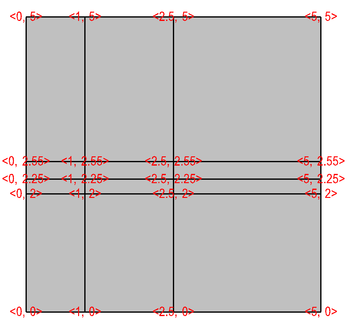
Fig. 10.41 Rectilinear mesh and its X,Y node coordinates.
A rectilinear mesh is a 2D or 3D mesh where all coordinates are aligned with the axes. Each axis of the rectilinear mesh can have different, non-uniform spacing, allowing for details to be concentrated in certain regions of the mesh. Rectilinear meshes are specified by lists of coordinate values for each axis. Since the mesh is aligned to the axes, it is only necessary to specify one set of X, Y, and Z values to generate all of the coordinates for the entire mesh.
Once you read the X,Y, and Z coordinates from your data file, you can use them to assemble a vtkRectilinearGrid object. The procedure for creating a vtkRectilinearGrid object and returning it from GetMesh is shown in the next code listing. The capitalized portions of the code listing indicate incomplete code that you must replace with code to read values from your file format. The first such piece requires you to read the number of dimensions for your mesh from the file format and store the value into the ndims variable. Once you have done that, read the number of nodes in each of the X,Y,Z dimensions and store those values in the dims array. Finally, fill in the code for reading the X coordinate values into the xarray array and do the same for the Y and Z coordinate arrays. Once you have replaced the capitalized code portions with code that reads values from your file format, your plugin should be able to return a valid vtkRectilinearGrid object once you rebuild it.
Example for creating vtkRectilinearGrid in GetMesh.
// NOTE - This code is incomplete and requires capitalized portions
// to be replaced with code to read values from your file format.
#include <vtkFloatArray.h>
#include <vtkRectilinearGrid.h>

vtkDataSet *
avtXXXFileFormat::GetMesh(const char *meshname)
{
    int ndims = 2;
    int dims[3] = {1,1,1};
    vtkFloatArray *coords[3] = {0,0,0};
    // Read the ndims and number of X,Y,Z nodes from file.
    ndims = NUMBER OF MESH DIMENSIONS;
    dims[0] = NUMBER OF NODES IN X-DIMENSION;
    dims[1] = NUMBER OF NODES IN Y-DIMENSION;
    dims[2] = NUMBER OF NODES IN Z-DIMENSION, OR 1 IF 2D;
    // Read the X coordinates from the file.
    coords[0] = vtkFloatArray::New();
    coords[0]->SetNumberOfTuples(dims[0]);
    float *xarray = (float *)coords[0]->GetVoidPointer(0);
    READ dims[0] FLOAT VALUES INTO xarray
    // Read the Y coordinates from the file.
    coords[1] = vtkFloatArray::New();
    coords[1]->SetNumberOfTuples(dims[1]);
    float *yarray = (float *)coords[1]->GetVoidPointer(0);
    READ dims[1] FLOAT VALUES INTO yarray
    // Read the Z coordinates from the file.
    coords[2] = vtkFloatArray::New();
    if(ndims > 2)
    {
        coords[2]->SetNumberOfTuples(dims[2]);
        float *zarray = (float *)coords[2]->GetVoidPointer(0);
        READ dims[2] FLOAT VALUES INTO zarray
    }
    else
    {
        coords[2]->SetNumberOfTuples(1);
        coords[2]->SetComponent(0, 0, 0.);
    }

    //
    // Create the vtkRectilinearGrid object and set its dimensions
    // and coordinates.
    //
    vtkRectilinearGrid *rgrid = vtkRectilinearGrid::New();
    rgrid->SetDimensions(dims);
    rgrid->SetXCoordinates(coords[0]);
    coords[0]->Delete();
    rgrid->SetYCoordinates(coords[1]);
    coords[1]->Delete();
    rgrid->SetZCoordinates(coords[2]);
    coords[2]->Delete();
    return rgrid;
}
10.7.5.3. Curvilinear meshes
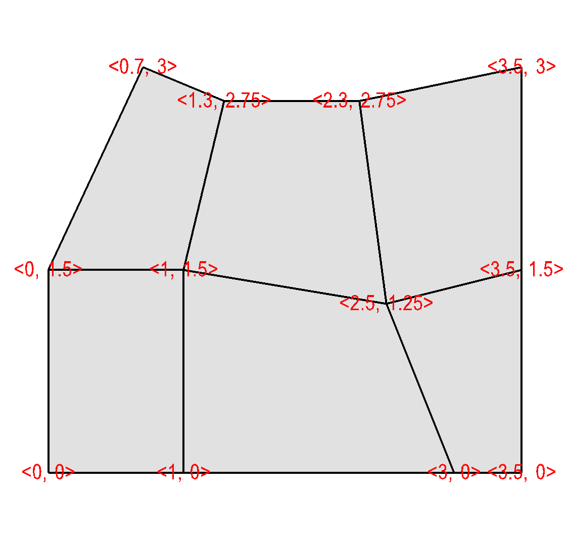
Fig. 10.42 Curvilinear mesh
Curvilinear meshes are structured meshes as are rectilinear meshes. While in a rectilinear mesh, a small set of independent X,Y,Z coordinate arrays are used to generate the coordinate values for each node in the mesh, in a curvilinear mesh, the node coordinates are explicitly given for each node in the mesh. This means that the sizes of the X,Y,Z coordinate arrays in a curvilinear mesh are all NX*NY*NZ where NX is the number of nodes in the Xdimension, NY is the number of nodes in the Y-dimension, and NZ is the number of nodes in the Z-dimension. Providing the coordinates for every node permits you to create more complex geometries than are possible using rectilinear meshes (See Figure 10.42).
Curvilinear meshes are created using the vtkStructuredGrid class. The next code listing shows how to create a vtkStructuredGrid object once you have read the required information from your file format. The capitalized portions of the code listing indicate incomplete code that you will need to replace with code that can read data from your file format. First, read the number of dimensions for your mesh from the file format and store the value into the ndims variable. Once you have done that, read the number of nodes in each of the X,Y,Z dimensions and store those values in the dims array. Finally, fill in the code for reading the X coordinate values into the xarray array and do the same for the Y and Z coordinate arrays. Once you have replaced the capitalized code portions with code that reads values from your file format, your plugin should be able to return a valid vtkStructuredGrid object once you rebuild it.
Example for creating vtkStructuredGrid in GetMesh.
// NOTE - This code is incomplete and requires capitalized portions
// to be replaced with code to read values from your file format.

#include <vtkPoints.h>
#include <vtkStructuredGrid.h>

vtkDataSet *
avtXXXFileFormat::GetMesh(const char *meshname)
{
    int ndims = 2;
    int dims[3] = {1,1,1};
    ndims = NUMBER OF MESH DIMENSIONS;
    dims[0] = NUMBER OF NODES IN X-DIMENSION;
    dims[1] = NUMBER OF NODES IN Y-DIMENSION;
    dims[2] = NUMBER OF NODES IN Z-DIMENSION, OR 1 IF 2D;
    int nnodes = dims[0]*dims[1]*dims[2];
    // Read the X coordinates from the file.
    float *xarray = new float[nnodes];
    READ nnodes FLOAT VALUES INTO xarray
    // Read the Y coordinates from the file.
    float *yarray = new float[nnodes];
    READ nnodes FLOAT VALUES INTO yarray
    // Read the Z coordinates from the file.
    float *zarray = 0;
    if(ndims > 2  )
    {
        zarray = new float[nnodes];
        READ dims[2] FLOAT VALUES INTO zarray
    }
    //
    // Create the vtkStructuredGrid and vtkPoints objects.
    //
    vtkStructuredGrid *sgrid = vtkStructuredGrid::New();
    vtkPoints *points = vtkPoints::New();
    sgrid->SetPoints(points);
    sgrid->SetDimensions(dims);
    points->Delete();
    points->SetNumberOfPoints(nnodes);
    //
    // Copy the coordinate values into the vtkPoints object.
    //
    float *pts = (float *) points->GetVoidPointer(0);
    float *xc = xarray;
    float *yc = yarray;
    float *zc = zarray;
    if(ndims == 3)
    {
        for(int k = 0; k < dims[2]; ++k)
            for(int j = 0; j < dims[1]; ++j)
                for(int i = 0; i < dims[0]; ++i)
                {
                    *pts++ = *xc++;
                    *pts++ = *yc++;
                    *pts++ = *zc++;
                }
    }
    else if(ndims == 2)
    {
        for(int j = 0; j < dims[1]; ++j)
            for(int i = 0; i < dims[0]; ++i)
            {
                *pts++ = *xc++;
                *pts++ = *yc++;
                *pts++ = 0.;
            }
    }
    // Delete temporary arrays.
    delete [] xarray;
    delete [] yarray;
    delete [] zarray;
    return sgrid;
}
10.7.5.4. Point meshes
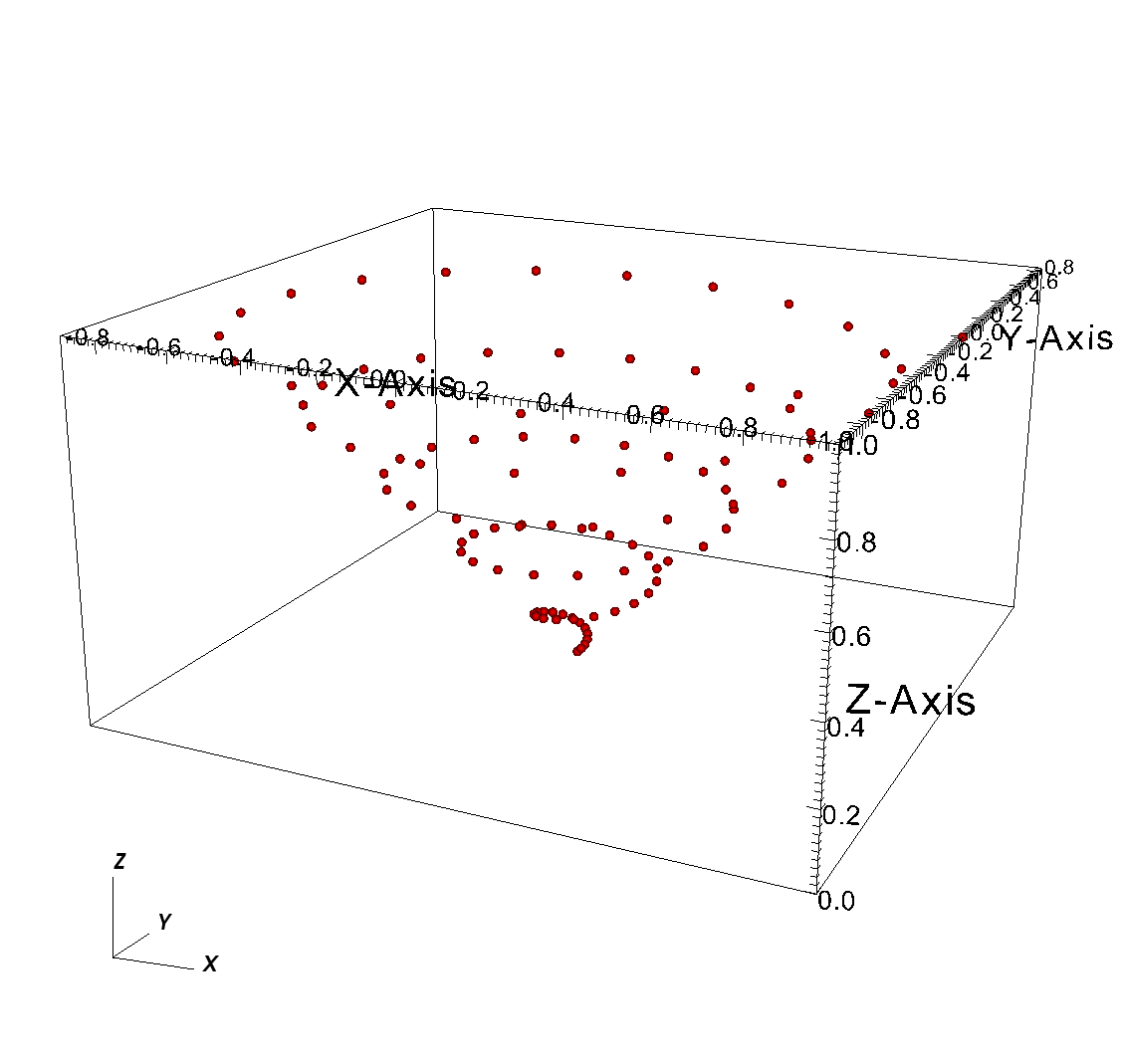
Point meshes are collections of particle positions that can be displayed in VisIt as points or small glyphed icons. Point meshes can be returned from the GetMesh method as vtkUnstructuredGrid objects that contain the locations of the points and connectivity composed entirely of vertex cells. The next code listing shows how to create a vtkUnstructuredGrid object once you have read the required information from your file format. The capitalized portions of the code listing indicate incomplete code that you will need to replace with code that can read data from your file format. First, read the number of dimensions for your mesh from the file format and store the value into the ndims variable. Next, read the number of points that make up the point mesh into the nnodes variable. Finally, fill in the code for reading the X coordinate values into the xarray array and do the same for the Y and Z coordinate arrays. Once you have replaced the capitalized code portions with code that reads values from your file format, your plugin should be able to return a valid vtkUnstructuredGrid object once you rebuild it.
Example for returning a point mesh from GetMesh
// NOTE - This code is incomplete and requires capitalized portions
// to be replaced with code to read values from your file format.

#include <vtkPoints.h>
#include <vtkUnstructuredGrid.h>

vtkDataSet *
avtXXXFileFormat::GetMesh(const char *meshname)
{
    int ndims = 2;
    int nnodes;
    // Read the ndims and number of nodes from file.
    ndims = NUMBER OF MESH DIMENSIONS;
    nnodes = NUMBER OF NODES IN THE MESH;
    // Read the X coordinates from the file.
    float *xarray = new float[nnodes];
    READ nnodes FLOAT VALUES INTO xarray
    // Read the Y coordinates from the file.
    float *yarray = new float[nnodes];
    READ nnodes FLOAT VALUES INTO yarray
    // Read the Z coordinates from the file.
    float *zarray = 0;
    if(ndims > 2)
    {
        zarray = new float[nnodes];
        READ dims[2] FLOAT VALUES INTO zarray
    }
    //
    // Create the vtkPoints object and copy points into it.
    //
    vtkPoints *points = vtkPoints::New();
    points->SetNumberOfPoints(nnodes);
    float *pts = (float *) points->GetVoidPointer(0);
    float *xc = xarray;
    float *yc = yarray;
    float *zc = zarray;
    if(ndims == 3)
    {
        for(int i = 0; i < nnodes; ++i)
        {
            *pts++ = *xc++;
            *pts++ = *yc++;
            *pts++ = *zc++;
        }
    }
    else if(ndims == 2)
    {
        for(int i = 0; i < nnodes; ++i)
        {
            *pts++ = *xc++;
            *pts++ = *yc++;
            *pts++ = 0.;
        }
    }
    //
    // Create a vtkUnstructuredGrid to contain the point cells.
    //
    vtkUnstructuredGrid *ugrid = vtkUnstructuredGrid::New();
    ugrid->SetPoints(points);
    points->Delete();
    ugrid->Allocate(nnodes);
    vtkIdType onevertex;
    for(int i = 0; i < nnodes; ++i)
    {
        onevertex = i;
        ugrid->InsertNextCell(VTK_VERTEX, 1, &onevertex);
    }
    // Delete temporary arrays.
    delete [] xarray;
    delete [] yarray;
    delete [] zarray;
    return ugrid;
}
10.7.5.5. Unstructured meshes
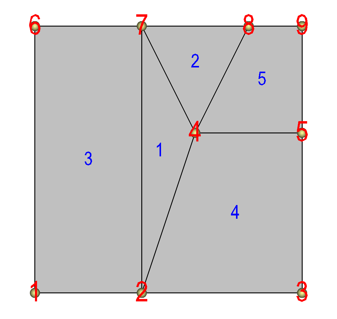
Fig. 10.43 Unstructured mesh
Unstructured meshes are collections of cells of various geometries that are specified using indices into an array of points. When you write your GetMesh method, if your mesh is best described as an unstructured mesh then you can return a vtkUnstructuredGrid object. Like some of the other mesh objects, the vtkUnstructuredGrid object also uses a vtkPoints object to contain its node array. In addition to the vtkPoints array, the vtkUnstructuredGrid object maintains a list of cells whose connectivity is determined by setting the cell type to one of VTK’s predefined unstructured cell types (VTK_VERTEX, VTK_LINE, VTK_TRIANGLE, VTK_QUAD, VTK_TETRA, VTK_PYRAMID, VTK_WEDGE, VTK_HEXAHEDRON, etc). More information on these cell types and more can be found in VTK’s Cell types docs. Keep in mind that VisIt may not fully support all of the higher-order cell types. When you add a cell using one of the predefined unstructured cell types, you must also provide a list of node indices that are used as the nodes for the cell. The number of nodes that each cell contains is determined by its cell type.
The next code listing shows how to create a vtkUnstructuredGrid object. The connectivity for an unstructured grid can be stored in a file format using a myriad of different approaches. The example code assumes that the connectivity will be stored in an integer array that contains the information for each cell, beginning with the cell type for the first cell, followed by a list of node indices that are used in the cell. After that, the cell type for the second cell appears, followed by its node indices, and so on. For example, if you wanted to store connectivity for cells 1 and 2 in the example shown in Figure 10.43 then the connectivity array would contain: [VTK_TRIANGLE, 2, 4, 7, VTK_TRIANGLE, 4, 8, 7, …]. Note that the node indices in the example begin at one so the example code will subtract one from all of the node indices to ensure that they begin at zero, the starting index for the vtkPoints array.
Example for returning an unstructured mesh from GetMesh.
// NOTE - This code is incomplete and requires capitalized portions
// to be replaced with code to read values from your file format.

#include <vtkPoints.h>
#include <vtkUnstructuredGrid.h>
#include <InvalidVariableException.h>

vtkDataSet *
avtXXXFileFormat::GetMesh(const char *meshname)
{
    int ndims = 2;
    int nnodes, ncells, origin = 1;
    // Read the ndims, nnodes, ncells, origin from file.
    ndims = NUMBER OF MESH DIMENSIONS;
    nnodes = NUMBER OF NODES IN THE MESH;
    ncells = NUMBER OF CELLS IN THE MESH;
    origin = GET THE ARRAY ORIGIN (0 or 1);
    // Read the X coordinates from the file.
    float *xarray = new float[nnodes];
    READ nnodes FLOAT VALUES INTO xarray
    // Read the Y coordinates from the file.
    float *yarray = new float[nnodes];
    READ nnodes FLOAT VALUES INTO yarray
    // Read the Z coordinates from the file.
    float *zarray = 0;
    if(ndims > 2)
    {
        zarray = new float[nnodes];
        READ dims[2] FLOAT VALUES INTO zarray
    }
    // Read in the connectivity array. This example assumes that
    // the connectivity will be stored: type, indices, type,
    // indices, ... and that there will be a type/index list
    // pair for each cell in the mesh.
    int *connectivity = 0;
    ALLOCATE connectivity ARRAY AND READ VALUES INTO IT.
    //
    // Create the vtkPoints object and copy points into it.
    //
    vtkPoints *points = vtkPoints::New();
    points->SetNumberOfPoints(nnodes);
    float *pts = (float *) points->GetVoidPointer(0);
    float *xc = xarray;
    float *yc = yarray;
    float *zc = zarray;
    if(ndims == 3)
    {
        for(int i = 0; i < nnodes; ++i)
        {
            *pts++ = *xc++;
            *pts++ = *yc++;
            *pts++ = *zc++;
        }
    }
    else if(ndims == 2)
    {
        for(int i = 0; i < nnodes; ++i)
        {
            *pts++ = *xc++;
            *pts++ = *yc++;
            *pts++ = 0.;
        }
    }
    // Delete temporary arrays.
    delete [] xarray;
    delete [] yarray;
    delete [] zarray;
    //
    // Create a vtkUnstructuredGrid to contain the point cells.
    //
    vtkUnstructuredGrid *ugrid = vtkUnstructuredGrid::New();
    ugrid->SetPoints(points);
    points->Delete();
    ugrid->Allocate(ncells);
    vtkIdType verts[8];
    int *conn = connectivity
    for(int i = 0; i < ncells; ++i)
    {
        int fileCellType = *conn++;
        // Your file's cellType will likely not match so you
        // will have to translate fileCellType to a VTK
        // cell type.
        int cellType = MAP fileCellType TO VTK CELL TYPE.
        // Determine number of vertices for each cell type.
        if(cellType == VTK_VERTEX)
            nverts = 1;
        else if(cellType == VTK_LINE)
            nverts = 2;
        else if(cellType == VTK_TRIANGLE)
            nverts = 3;
        else if(cellType == VTK_QUAD)
            nverts = 4;
        else if(cellType == VTK_TETRA)
            nverts = 4;
        else if(cellType == VTK_PYRAMID)
            nverts = 5;
        else if(cellType == VTK_WEDGE)
            nverts = 6;
        else if(cellType == VTK_HEXAHEDRON)
            nverts = 8;
        else
        {
            delete [] connectivity;
            ugrid->Delete();
            // Other cell type - need to add a case for it.
            // In the meantime, throw exception or if you
            // know enough, skip the cell.
            EXCEPTION0(InvalidVariableException, meshname);
        }
        // Make a list of node indices that make up the cell.
        for(int j = 0; j < nverts; ++j)
            verts[j] = conn[j] - origin;
        conn += nverts;
        // Insert the cell into the mesh.
        ugrid->InsertNextCell(cellType, nverts, verts);
    }
    delete [] connectivity;
    return ugrid;
}
The previous code listing shows how to create an unstructured mesh in a vtkUnstructuredGrid object. The code listing contains capitalized portions that you must replace with working code to read the relevant data from your file format. The first instance of code that must be replaced are the lines that read ndims, nnodes, ncells, and origin from the file format. The ndims variable should contain 2 or 3, depending on whether your data is 2D or 3D. The nnodes variable should contain the number of nodes that are used in the set of vertices that describe your unstructured mesh. The ncells variable should contain the number of cells that will be added to your unstructured mesh. The origin variable should contain 0 or 1, depending on whether your connectivity indices begin at 0 or 1. Once you have set those variables to the appropriate values, you must read in the X, Y, and Z coordinate arrays from the file format and store the values into the xarray, yarray, and zarray array variables. If your file format keeps X,Y,Z values together in a single array then you may be able to read the coordinate values directly into the vtkPoints object’s memory, skipping the step of copying the X,Y,Z coordinate components into the vtkPoints object. After reading in the coordinate values from your file format, unstructured meshes require two more changes to the code in the listing. The next change requires you to allocate memory for a connectivity array, which stores the type of cells and the nodes indices of the nodes that are used in the cells. The final change that you must make to the source code in the listing is located further down in the loop that adds cells to the vtkUnstructuredGrid object. The cell type read from your file format will most likely not use the same enumerated type values that VTK uses for its cell types (VTK_VERTEX, VTK_LINE, …) so you will need to add code to translate from your cell type designation to VTK cell type numbers. After making the necessary changes and rebuilding your plugin, your plugin’s GetMesh method should be capable of returning a valid vtkUnstructuredGrid object for VisIt to plot.
10.7.6. Returning a scalar variable
Now that you can successfully create a Mesh plot of the meshes from your file format, you can focus on other types of data such as scalars. If you exposed scalar variables in your plugin’s PopulateDatabaseMetaData method then those variable names will appear in the plot menus for plots that can use scalar variables (e.g. the Pseudocolor plot). When you create a plot of a scalar variable and click the Draw button in the GUI, VisIt will tell your database reader plugin to open your file, read the mesh, and then your plugin’s GetVar method will be called with the name of the variable that you want to plot. The GetVar method, like the GetMesh method, takes a variable name as an argument. When you receive the variable name in the GetVar method you should access your file and read out the desired variable and return it in a VTK data array such as a vtkFloatArray or a vtkDoubleArray. A vtkFloatArray is a VTK object that encapsulates a dynamically allocated array of a given length. The length of the array that you allocate to contain your variable must match either the number of cells in your mesh or the number of nodes in your mesh. The length is determined by the scalar variable’s centering (cell-centered, node-centered).
Example for returning data from GetVar.
// NOTE - This code is incomplete and requires capitalized portions
// to be replaced with code to read values from your file format.

#include <vtkFloatArray.h>

vtkDataArray *
avtXXXFileFormat::GetVar(const char *varname)
{
    int nvals;
    // Read the number of vaues contained in the array
    // specified by varname.
    nvals = NUMBER OF VALUES IN ARRAY NAMED BY varname;
    // Allocate the return vtkFloatArray object. Note that
    // you can use vtkFloatArray, vtkDoubleArray,
    // vtkUnsignedCharArray, vtkIntArray, etc.
    vtkFloatArray *arr = vtkFloatArray::New();
    arr->SetNumberOfTuples(nvals);
    float *data = (float *)arr->GetVoidPointer(0);
    READ nvals FLOAT NUMBERS INTO THE data ARRAY.
    return arr;
}
In the previous code listing, there are two capitalized areas that need to have code added to them in order to have a completed GetVar method. The first change that you must make is to add code to read the size of the array to be created into the nvals variable. The value that is read into the nvals variable must be either the number of cells in the mesh on which the variable is defined if you have a cell-centered variable or it must be the number of nodes in the mesh. Once you have successfully set the proper value into the nvals variable, you can proceed to read values from your file format into the data array, which points to storage owned by the vtkFloatArray object that will be returned from the GetVar method. Once you have made these changes, you can rebuild your plugin and begin plotting scalar variables.
10.7.7. Returning a vector variable
The mechanism for returning a vector variable the same as returning a scalar variable, except in the number of components in each tuple of the vtkFloatArray or vtkDoubleArray. If you exposed vector variables in your plugin’s PopulateDatabaseMetaData method then those variable names will appear in the plot menus for plots that can use vector variables (e.g. the Vector plot). The length of the array that you allocate to contain your variable must match either the number of cells in your mesh or the number of nodes in your mesh. The length is determined by the vector variable’s centering (cell-centered, node-centered). In addition to setting the length, which like a scalar variable is tied to the number of cells or nodes, you must also set the number of vector components. In VisIt, vector variables always have three components. If the third component is not needed then all values in the third component should be set to zero. The GetVectorVar code listing shows how to return a vtkFloatArray with multiple components from the GetVectorVar method. As with the code listing for GetVar, this code listing requires you to replace capitalized lines of code with code that reads data from your file format and stores the results in the variables provided.
Example for returning data from GetVectorVar.
// NOTE - This code is incomplete and requires capitalized portions
// to be replaced with code to read values from your file format.

#include <vtkFloatArray.h>
#include <InvalidVariableException.h>

vtkDataArray *
avtXXXFileFormat::GetVectorVar(const char *varname)
{
    int nvals, ncomps = 3;
    // Read the number of values contained in the array
    // specified by varname.
    nvals = NUMBER OF VALUES IN ARRAY NAMED BY varname;
    ncomps = NUMBER OF VECTOR COMPONENTS IN ARRAY NAMED BY varname;
    // Read component 1 from the file.
    float *comp1 = new float[nvals];
    READ nvals FLOAT VALUES INTO comp1
    // Read component 2 from the file.
    float *comp2 = new float[nvals];
    READ nvals FLOAT VALUES INTO comp2
    // Read component 3 from the file.
    float *comp3 = 0;
    if(ncomps > 2)
    {
        comp3 = new float[nvals];
        READ nvals FLOAT VALUES INTO comp3
    }
    // Allocate the return vtkFloatArray object. Note that
    // you can use vtkFloatArray, vtkDoubleArray,
    // vtkUnsignedCharArray, vtkIntArray, etc.
    vtkFloatArray *arr = vtkFloatArray::New();
    arr->SetNumberOfComponents(3);
    arr->SetNumberOfTuples(nvals);
    float *data = (float *)arr->GetVoidPointer(0);
    float *c1 = comp1;
    float *c2 = comp2;
    float *c3 = comp3;
    if(ncomps == 3)
    {
        for(int i = 0; i < nvals; ++i)
        {
            *data++ = *c1++;
            *data++ = *c2++;
            *data++ = *c3++;
        }
    }
    else if(ncomps == 2)
    {
        for(int i = 0; i < nvals; ++i)
        {
            *data++ = *c1++;
            *data++ = *c2++;
            *data++ = 0.;
        }
    }
    else
    {
        delete [] comp1;
        delete [] comp2;
        delete [] comp3;
        arr->Delete();
        EXCEPTION1(InvalidVariableException, varname);
    }
    // Delete temporary arrays.
    delete [] comp1;
    delete [] comp2;
    delete [] comp3;

    return arr;
}
10.7.8. Using a VTK reader class
The implementations so far for the GetMesh, GetVar, and GetVectorVar plugin methods have assumed that the database plugin would do the work of interacting with the file format to read data into VTK form. Most of the work of reading a file and creating VTK objects from it can be handled at the VTK level if you wish. This means that it is possible to use an existing VTK reader class to read data into VisIt if you are willing to implement your plugin methods so that they in turn call the VTK reader object’s methods. See VisIt’s VTK database reader plugin for an example of how to call VTK reader objects from inside a VisIt database reader plugin.
10.8. Advanced topics
If you’ve implemented your database reader plugin using only the techniques outlined in this chapter so far then you likely have a database reader plugin that works and correctly serves up its data to VisIt in VTK form. This part of the chapter explains some of the more advanced, though not necessarily required, techniques that you can use to enhance your plugin. For instance, you can enhance your plugin so it returns the correct simulation times from the data files. You can also add code to return data and spatial extents for your data, enabling VisIt to make more optimization decisions when processing files with multiple domains.
10.8.1. Returning cycles and times
Simulations often iterate for many thousands of cycles while they solve their systems of equations. Generally, each simulation cycle has an associated cycle number and time value. Many file formats save this information so it can be made available later to post-processing tools such as VisIt. VisIt uses cycles and times to help you navigate through time in your database by providing the same time frame of reference that your simulation used. VisIt’s can show the current time value as you scroll through time using the time slider. Cycle and time values for the current timestate are often displayed in the visualization window. Returning cycle and time values from your plugin is completely optional. In fact, returning cycle and time values for data such as CAD drawings does not make sense. Since returning cycles and times is optional in a VisIt database reader plugin, you can choose to not implement the methods that return cycles and times. You can also implement code to return time but not cycles or vice-versa. The mechanics of returning cycles and times are a little different depending on whether you have written an ST or an MT database reader plugin. In any case, if your plugin implements the methods to return cycles or times then those methods will be some of the first methods called when VisIt accesses your database reader plugin. VisIt calls the methods to get cycles and times and if the returned values appear to be valid then they are added to the metadata for your file so they can be returned to the VisIt clients and used to populate windows such as the File Information window.
10.8.1.1. Returning cycles and times in an ST plugin
When VisIt creates plugin objects to handle a list of files using an ST plugin, there is one plugin object per file in the list of files. Since each plugin object can only ever be associated with one file, the programming interface for returning cycles and times for an ST plugin provides methods that return a single value. The methods for returning cycles and times for an ST plugin are:
virtual bool ReturnsValidCycle() const { return true; }
virtual int GetCycle(void);
virtual bool ReturnsValidTime() const { return true; }
virtual double GetTime(void);
Implementing valid cycles and times can be done independently of one another and there is no requirement that you have to implement both or either of them, for that matter. The ReturnsValidCycle method is a simple method that you should expose if you plan to provide a custom GetCycle method in your database reader plugin. If you provide GetCycle then the ReturnsValidCycle method should return true. The same pattern applies if you implement GetTime - except that you would also implement the ReturnsValidTime method. Replace the capitalized sections of code in the listing with code to read the correct cycle and time values from your file format.
Example for returning cycles, times from ST plugin.
// NOTE - This code is incomplete and requires capitalized portions
// to be replaced with code to read values from your file format.

int
avtXXXFileFormat::GetCycle(void)
{
    int cycle = OPEN FILE AND READ THE CYCLE VALUE;
    return cycle;
}

double
avtXXXFileFormat::GetTime(void)
{
    double dtime = OPEN FILE AND READ THE TIME VALUE;
    return dtime;
}
In the event that you implement the GetCycle method but no cycle value is available in the file, you can return the INVALID_CYCLE value to make VisIt discard your plugin’s cycle number and guess the cycle number from the filename. If you want VisIt to successfully guess the cycle number from the filename then you must implement the GetCycleFromFilename method.
int
avtXXXXFileFormat::GetCycleFromFilename(const char *f) const
{
    return GuessCycle(f);
}
10.8.1.2. Returning cycles and times in an MT plugin
An MT database reader plugin may return cycles and times for multiple timestates so the programming interface for MT plugins allows you to return vectors of cycles and times. In addition, an MT database reader plugin prefers to know upfront how many timestates will be returned from the file format so in addition to GetCycles and GetTimes methods, there is a GetNTimesteps method that is among the first methods called from your database reader plugin.
virtual void GetCycles(std::vector<int> &);
virtual void GetTimes(std::vector<double> &);
virtual int GetNTimesteps(void);
As with ST plugins, there is no requirement that an MT plugin must provide a list of cycles or times. However, an MT plugin must provide a GetNTimesteps method. If you are enhancing your database reader plugin to return cycles and times then it is convenient to implement your GetNTimesteps method such that it just calls your GetCycles or GetTimes method and returns the length of the vector returned by those methods. This simplifies the implementation and ensures that the number of timestates reported by your database reader plugin matches the length of the cycle and time vectors returned from GetCycles and GetTimes. Replace the capitalized sections of code in the listing with code to read the correct cycles and times from your file format.
Example for returning cycles, times from MT plugin.
// NOTE - This code is incomplete and requires capitalized portions
// to be replaced with code to read values from your file format.
void
avtXXXFileFormat::GetCycles(std::vector<int> &cycles)
{
int ncycles, *vals = 0;
ncycles = OPEN FILE AND READ THE NUMBER OF CYCLES;
READ ncycles INTEGER VALUES INTO THE vals ARRAY;
// Store the cycles in the vector.
for(int i = 0; i < ncycles; ++i)
cycles.push_back(vals[i]);
delete [] vals;
}
void
avtXXXFileFormat::GetTime(std::vector<double> ×)
{
int ntimes;
double *vals = 0;
ntimes = OPEN FILE AND READ THE NUMBER OF TIMES;
READ ntimes DOUBLE VALUES INTO THE vals ARRAY;
// Store the times in the vector.
for(int i = 0; i < ntimes; ++i)
times.push_back(vals[i]);
delete [] vals;
}
int
avtXXXXFileFormat::GetNTimesteps(void)
{
std::vector<double> times;
GetTimes(times);
return times.size();
}
10.8.2. Auxiliary data
This section describes how to enable your MD database reader plugin so it can provide auxiliary data such as data extents, spatial extents, and materials to VisIt if they are available in your file format. “Auxiliary data” is the generic term for many types of data that VisIt’s pipeline can use to perform specific tasks such as I/O reduction or material selection. VisIt’s database reader plugin interfaces provide a method called GetAuxiliaryData that you can implement if you want your plugin to be capable of returning auxiliary data. Note however that if your plugin is MTMD then you will have to cache your spatial and data extents in the plugin’s variable cache in the PopulateDatabaseMetaData method instead of returning that information from the GetAuxiliaryData method. This subtle difference in how certain metadata is accessed by VisIt must be observed by an MTMD plugin in order for it to return spatial and data extents.
The method arguments for the GetAuxiliaryData method may vary somewhat depending on whether your database reader plugin is based on the STSD, STMD, MTSD, MTMD interfaces. There is an extra integer argument for the timestate if your plugin is MT and there is another integer argument for the domain if your plugin is MD. Those differences aside, the GetAuxiliaryData method always accepts the name of a variable, a string indicating the type of data being requested, a pointer to optional data required by the type of auxiliary data being requested, and a return reference for a destructor function that will be responsible for freeing resources for the returned data. The variable name that VisIt passes to the GetAuxiliaryData method is the name of a variable such as those passed to the GetVar method when VisIt wants to read a variable’s data.
10.8.2.1. Returning data extents
When an MD database reader plugin provides data extents for each of its domains, VisIt has enough information to make important optimization decisions in filters that support data extents. For example, if you create a Contour plot using a specific contour value, VisIt can check the data extents for each domain before any domains are read from disk and determine the list of domains that contain the desired contour value. After determining which subset of the domains will contribute to the final image, VisIt’s compute engine then reads and processes only those domains, saving work and accelerating VisIt’s computations. For a more complete explanation of data extents, see Writing data extents.
In the context of returning data extents, VisIt first checks a plugin’s variable cache for extents. If the desired extents are not available then VisIt calls the plugin’s GetAuxiliaryData method with the name of the scalar variable for which data extents are required and also passes AUXILIARY_DATA_DATA_EXTENTS as the type argument, indicating that the GetAuxiliaryData method is being called to obtain the data extents for the specified scalar variable. If the data extents for the specified variable are not available then the GetAuxiliaryData method should return 0. If the data extents are available then the list of minimum and maximum values for the specified variable are assembled into an interval tree structure that VisIt uses for fast comparisons of different data ranges. Once the interval tree is constructed, as shown in the code listing, the GetAuxiliaryData method must return the interval tree object and set the destructor function argument to a function that can be called to later destroy the interval tree. To add support for data extents to your database reader plugin, copy the GetAuxiliaryData method in the code listing and replace the capitalized lines of code with code that reads the required information from your file format.
Example for returning data extents.
// NOTE - This code is incomplete and requires capitalized portions
// to be replaced with code to read values from your file format.

#include <avtIntervalTree.h>

// STMD version of GetAuxiliaryData.

void *
avtXXXXFileFormat::GetAuxiliaryData(const char *var,
    int domain, const char *type, void *,
    DestructorFunction &df)
{
    void *retval = 0;
    if(strcmp(type, AUXILIARY_DATA_DATA_EXTENTS) == 0)
    {
        // Read the number of domains for the mesh.
        int ndoms = READ NUMBER OF DOMAINS FROM FILE;
        // Read the min/max values for each domain of the
        // "var" variable. This information should be in
        // a single file and should be available without
        // having to read the real data.
        double *minvals = new double[ndoms];
        double *maxvals = new double[ndoms];
        READ ndoms DOUBLE VALUES INTO minvals ARRAY.
        READ ndoms DOUBLE VALUES INTO maxvals ARRAY.
        // Create an interval tree
        avtIntervalTree *itree = new avtIntervalTree(ndoms, 1);
        for(int dom = 0; dom < ndoms; ++dom)
        {
            double range[2];
            range[0] = minvals[dom];
            range[1] = maxvals[dom];
            itree->AddElement(dom, range);
        }
        itree->Calculate(true);
        // Delete temporary arrays.
        delete [] minvals;
        delete [] maxvals;
        // Set return values
        retval = (void *)itree;
        df = avtIntervalTree::Destruct;
    }
    return retval;
}
10.8.2.2. Returning spatial extents
Another type of auxiliary data that VisIt supports for MD file formats are spatial extents. When VisIt knows the spatial extents for all of the domains that comprise a mesh, VisIt can optimize operations such as the Slice operator by first determining whether the slice will intersect a given domain. The Slice operator is thus able to use spatial extents to determine which set of domains must be read from disk and processed in order to produce the correct visualization. Spatial extents are used in this way by many filters to reduce the set of domains that must be processed. When VisIt asks the database reader plugin for spatial extents, the GetAuxiliaryData method is called with its type argument set to AUXILIARY_DATA_SPATIAL_EXTENTS. When VisIt creates spatial extents, they are stored in an interval tree structure as they are with data extents. The main difference is the input into the interval tree. When adding information about a specific domain to the interval tree, you must provide the minimum and maximum spatial values for the domain’s X, Y, and Z dimensions. The spatial extents for one domain are expected to be provided in the following order: xmin, xmax, ymin, ymax, zmin, zmax. To add support for spatial extents to your database reader plugin, copy the GetAuxiliaryData method in the code listing and replace the capitalized lines of code with code that reads the required information from your file format.
Example for returning spatial extents.
// NOTE - This code is incomplete and requires capitalized portions
// to be replaced with code to read values from your file format.

#include <avtIntervalTree.h>

// STMD version of GetAuxiliaryData.

void *
avtXXXXFileFormat::GetAuxiliaryData(const char *var,
    int domain, const char *type, void *,
    DestructorFunction &df)
{
    void *retval = 0;
    if(strcmp(type, AUXILIARY_DATA_SPATIAL_EXTENTS) == 0)
    {
        // Read the number of domains for the mesh.
        int ndoms = READ NUMBER OF DOMAINS FROM FILE;
        // Read the spatial extents for each domain of the
        // mesh. This information should be in a single
        // and should be available without having to
        // read the real data. The expected format for
        // the data in the spatialextents array is to
        // repeat the following pattern for each domain:
        // xmin, xmax, ymin, ymax, zmin, zmax.
        double *spatialextents = new double[ndoms * 6];
        READ ndoms*6 DOUBLE VALUES INTO spatialextents ARRAY.
        // Create an interval tree
        avtIntervalTree *itree = new avtIntervalTree(ndoms, 3);
        double *extents = spatialextents;
        for(int dom = 0; dom < ndoms; ++dom)
        {
            itree->AddElement(dom, extents);
            extents += 6;
        }
        itree->Calculate(true);
        // Delete temporary array.
        delete [] spatialextents;
        // Set return values
        retval = (void *)itree;
        df = avtIntervalTree::Destruct;
    }
    return retval;
}
10.8.2.3. Returning materials
Materials are another type of auxiliary data that database plugins can provide. A material classifies different pieces of the mesh into different named subsets that can be turned on and off using VisIt’s Subset window. In the simplest case, you can think of a material as a cell-centered variable, or matlist, defined on your mesh where each cell contains an integer that identifies a particular material such as “Steel” or “Air”. VisIt’s avtMaterial object is used to encapsulate knowledge about materials. The avtMaterial object contains the matlist array and a list of names corresponding to each unique material number in the matlist array. Materials can also be structured so that instead of providing just one material number for each cell in the mesh, you can provide multiple materials per cell with volume fractions occupied by each. So-called “mixed materials” are created using additional arrays, described in Materials. To add support for materials in your database reader plugin’s GetAuxiliaryData method, replace the capitalized lines in the code example with code that read the necessary values from your file format.
Example for returning materials.
// NOTE - This code is incomplete and requires capitalized portions
// to be replaced with code to read values from your file format.

#include <avtMaterial.h>

// STMD version of GetAuxiliaryData.

void *
avtXXXXFileFormat::GetAuxiliaryData(const char *var,
    int domain, const char *type, void *,
    DestructorFunction &df)
{
    void *retval = 0;
    if(strcmp(type, AUXILIARY_DATA_MATERIAL) == 0)
    {
        int dims[3] = {1,1,1}, ndims = 1;
        // Structured mesh case
        ndims = MESH DIMENSION, 2 OR 3;
        dims[0] = NUMBER OF ZONES IN X DIMENSION;
        dims[1] = NUMBER OF ZONES IN Y DIMENSION;
        dims[2] = NUMBER OF ZONES IN Z DIMENSION, OR 1 IF 2D;
        // Unstructured mesh case
        dims[0] = NUMBER OF ZONES IN THE MESH
        ndims = 1;
        // Read the number of materials from the file. This
        // must have already been read from the file when
        // PopulateDatabaseMetaData was called.
        int nmats = NUMBER OF MATERIALS;
        // The matnos array contains the list of numbers that
        // are associated with particular materials. For example,
        // matnos[0] is the number that will be associated with
        // the first material and any time it is seen in the
        // matlist array, that number should be taken to mean
        // material 1. The numbers in the matnos array must
        // all be greater than or equal to 1.
        int *matnos = new int[nmats];
        READ nmats INTEGER VALUES INTO THE matnos ARRAY.
        // Read the material names from your file format or
        // make up names for the materials. Use the same
        // approach as when you created material names in
        // the PopulateDatabaseMetaData method.
        char **names = new char *[nmats];
        READ MATERIAL NAMES FROM YOUR FILE FORMAT UNTIL EACH
        ELEMENT OF THE names ARRAY POINTS TO ITS OWN STRING.
        // Read the matlist array, which tells what the material
        // is for each zone in the mesh.
        int nzones = dims[0] * dims[1] * dims[2];
        int *matlist = new int[nzones];
        READ nzones INTEGERS INTO THE matlist array.
        // Optionally create mix_mat, mix_next, mix_zone, mix_vf
        // arrays and read their contents from the file format.
        // Use the information to create an avtMaterial object.
        avtMaterial *mat = new avtMaterial(
            nmats,
            matnos,
            names,
            ndims,
            dims,
            0,
            matlist,
            0, // length of mix arrays
            0, // mix_mat array
            0, // mix_next array
            0, // mix_zone array
            0 // mix_vf array);

        // Clean up.
        delete [] matlist;
        delete [] matnos;
        for(int i = 0; i < nmats; ++i)
            delete [] names[i];
        delete [] names;
        // Set the return values.
        retval = (void *)mat;
        df = avtMaterial::Destruct;
    }
    return retval;
}
10.8.3. Returning ghost zones
Ghost zones are mesh zones that should not be visible in the visualization but may provide additional information such as values along domain boundaries. VisIt uses ghost zones for ensuring variable continuity across domain boundaries, for removing internal domain boundary faces, and for blanking out specific zones. This section covers the code that must be added to make your database reader plugin order for it to return ghost zones to VisIt.
10.8.3.1. Blanking out zones
Blanking out specific zones so they do not appear in a visualization is a common practice for creating holes in structured meshes so cells zones that overlap or tangle on top of one another can be removed from the mesh. If you want to create a mesh that contains voids where zones have been removed then you can add a special cell-centered array to your mesh before you return it from your plugin’s GetMesh method. The code in the listing can be used to remove zones from any mesh type and works by looking through a mesh-sized array containing on/off values for each zone and sets the appropriate values into the ghost zone array that gets added to the mesh object. Replace any capitalized code with code that can read the necessary values from your file format.
Example for returning ghost data.
// NOTE - This code is incomplete and requires capitalized portions
// to be replaced with code to read values from your file format.

#include <avtGhostData.h>
#include <vtkUnsignedCharArray.h>

vtkDataSet *
avtXXXXFileFormat::GetMesh(const char *meshname)
{
    // Code to create your mesh goes here.
    vtkDataSet *retval = CODE TO CREATE YOUR MESH;
    // Now that you have your mesh, figure out which cells need
    // to be removed.
    int nCells = retval->GetNumberOfCells();
    int *blanks = new int[nCells];
    READ nCells INTEGER VALUES INTO blanks ARRAY.
    // Now that we have the blanks array, create avtGhostZones.
    unsigned char realVal = 0, ghost = 0;
    avtGhostData::AddGhostZoneType(ghost, ZONE_NOT_APPLICABLE_TO_PROBLEM);
    vtkUnsignedCharArray *ghostCells = vtkUnsignedCharArray::New();
    ghostCells->SetName("avtGhostZones");
    ghostCells->Allocate(nCells);
    for(int i = 0; i < nCells; ++i)
    {
        if(blanks[i])
            ghostCells->InsertNextValue(realVal);
        else
            ghostCells->InsertNextValue(ghost);
    }

    retval->GetCellData()->AddArray(ghostCells);
    retval->SetUpdateGhostLevel(0);
    ghostCells->Delete();
    // Clean up
    delete [] blanks;
    return retval;
}
10.8.3.2. Ghost zones at the domain boundaries
When ghost zones are used to ensure continuity across domains, an extra layer of zones must be added to the mesh boundaries where the boundary is shared with another domain. Once you have done that step, the approach for providing ghost zones is the same as for blanking out cells using ghost zones if your blanks array contains zeroes for only the zones that appear on domain boundaries. The one minor difference is that you must substitute the DUPLICATED_ZONE_INTERNAL_TO_PROBLEM ghost zone type for the ZONE_NOT_APPLICABLE_TO_PROBLEM ghost zone type in the code example.
10.8.4. Parallelizing your reader
VisIt is a distributed program made up of multiple software processes that act as a whole. The software process that reads in data and processes it is the compute engine, which comes in serial and parallel versions. All of the libE plugins in VisIt also have both serial and parallel versions. The parallel libE plugins can contain specialized MPI communication to support the communication patterns needed by the algorithms used. If you want to parallelize your database reader plugin then, in most cases, you will have to use the MD interface or convert from SD to MD. There are some SD formats that can adaptively decompose their data so each processor has work (see the DDCMD plugin) but most database plugins that benefit from parallelism instead are implemented as MD plugins. MD plugins are a natural fit for the parallel compute engine because they serve data that is already decomposed into domains. Some database reader plugins, such as the BOV plugin, take single domain meshes and automatically decompose them into multiple domains for faster processing on multiple processors.
Deriving your plugin from an MD interface is useful since it naturally tells VisIt to expect data from more than one domain when reading your file format. There are a number of parallel optimizations that can be made inside of your MD database reader plugin. For example, you might have one processor read the metadata and broadcast it to all other processors so when you visualize your data with a large number of processors, they are not all trying to read the file that contains the metadata. VisIt’s parallel compute engine can use one of two different load balancing schemes: static or dynamic. In static load balancing, each processor is assigned a fixed list of domains and each of those domains is processed one at a time in parallel visualization pipelines until the result is computed. When static load balancing is used, the same code is executed on all processors with different data and there are more opportunities for parallel, global communication. When VisIt’s parallel compute engine uses dynamic load balancing, the master process acts as an executive that assigns work as needed to each processor. When a processor needs work, it requests a domain from the executive and it processes the domain in its visualization pipeline until the results for the domain have been calculated. After that, the processor asks the executive for another domain. In dynamic load balancing, each processor can be working on very different operations so there is no opportunity to do global communication. VisIt attempts to do dynamic load balancing unless any one of the filters in its visualization pipeline requires global communication, in which case static load balancing must be used. This means that the places where global communication can occur are few.
VisIt’s database plugin interfaces provide the ActivateTimestep method as a location where global, parallel communication can be performed safely. If your parallel database reader needs to do parallel communication such as broadcasting metadata to all processors, or figuring out data extents in parallel then that code must be added in the ActivateTimestep method.
10.8.5. Third party library support
If your plugin depends on an I/O library not already supported by VisIt, and if the plugin will be contributed to VisIt’s repo, then support for the library needs to be added to the build_visit script.
Please see Creating a build_visit Module for how to add a new module to build_visit.
A CMake Find module will also need to be added to src/CMake and src/CMake/SetupThirdParty.cmake will need to be modified to include that module.
See Adding a Find Module for Third Party Libraries for more information.