11.3. Plane Tool
The plane tool allows the user to see a representation of a slice plane in a visualization window and position the plane relative to plots that may exist in the window. The plane tool, shown in Figure 11.6, is represented as a set of 3D axes, a bounding rectangle, and text which gives the plane equation in origin-normal form. The plane tool provides several hot points positioned along the 3D axes that are used to position and orient the tool. The hot point nearest the origin allows the user to move the plane tool in a plane parallel to the computer screen. The hot point that lies in the middle of the plane’s Z-axis translates the plane tool along its normal vector when the hotpoint is dragged up and down. The hot point on the end of the Z-axis causes the plane tool to rotate freely when the hot point is moved. When the plane tool is facing into the screen, the Z-axis vector turns red to indicate which direction the plane tool is pointing. The other hot points also rotate the plane tool but they restrict the rotation to a single axis of rotation.
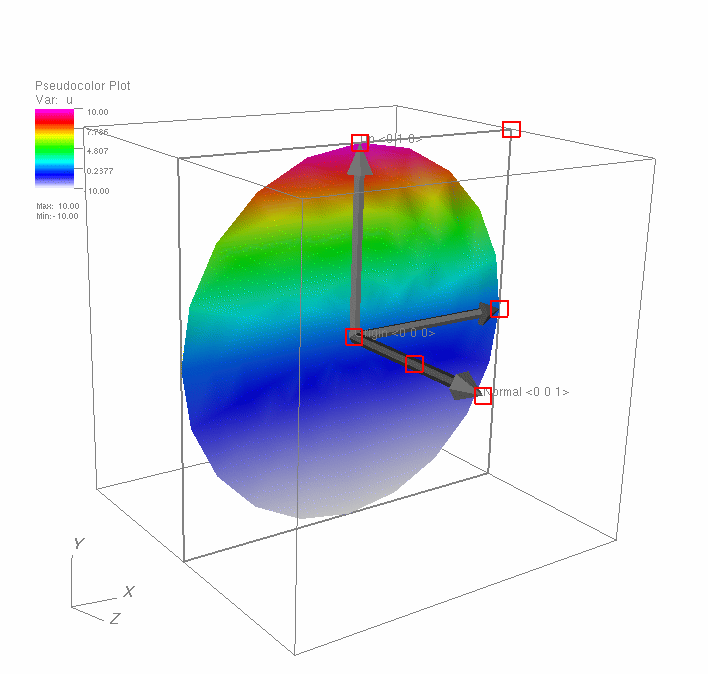
Fig. 11.6 Plane tool with sliced plot
You can use the plane tool to set the attributes for certain VisIt plots and operators. The Slice operator, for example, can update its plane equation from the plane tool’s plane equation. If a plot has a Slice operator applied to it, the plane tool is initialized with that operator’s slice plane when it is first enabled. As the plane tool is repositioned and reoriented, the plane tool’s plane equation is given to the operator and the sliced plot is recalculated.