4.3.24. Slice operator
This operator slices a 3D database with a plane that can have an arbitrary orientation. Plots to which the Slice operator has been applied are turned into 2D planar surfaces that are coplanar with the slice plane. The resulting plot can be left as a 2D slice in 3D space or it can be projected to 2D space where other operations can be done to it. A Pseudocolor plot to which a Slice operator has been applied is shown in Figure 4.56.
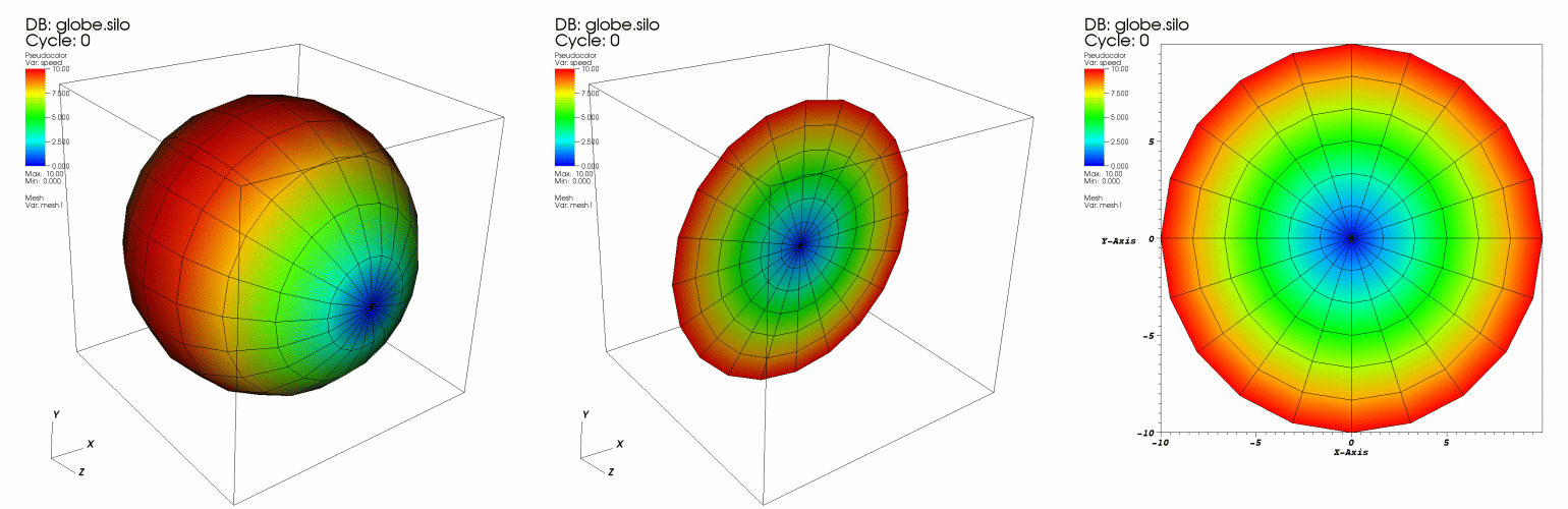
Fig. 4.56 Slice operator example
4.3.24.1. Positioning the slice plane
You can position the slice plane by setting the origin, normal, and up-axis vectors in the Slice operator attributes window, shown in Figure 4.57 . The slice plane is specified using the origin-normal form of a plane where all that is needed to specify the plane are two vectors; the origin and the normal. The origin of the plane is a point in the slice plane. The normal vector is a vector that is perpendicular to the slice plane.
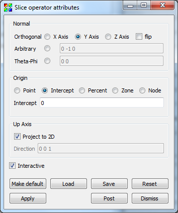
Fig. 4.57 Slice attributes window
VisIt allows the slice plane normal to be aligned to a specific axis or it can be set to any arbitrary vector. If you want the slice plane to be along any of the three axes, click the X-Axis, Y-Axis, or Z-Axis radio button. If you want to make a slice plane that does not align with the principle axes, click the Arbitrary or Theta-Phi radio button and then type a direction vector into the text field to the right of the radio button. The vector need not be normalized since VisIt will normalize the vector before using it.
The slice plane’s origin, which specifies the location of the slice plane, can be set five different ways. The middle of the Slice attributes window, or Origin area (see the Figures below), provides the necessary controls required to set the slice plane origin. The Origin area provides five radio buttons: Point, Intercept, Percent, Zone, and Node. Clicking on one of these radio buttons causes the Origin area to display the appropriate controls for setting the slice plane origin. To set the slice plane origin to a specific point, click the Point radio button in the Origin area and then type a new 3D point into the Point text field. To set the slice plane origin to a specific value along the principle slice axis (usually an orthogonal slice), click the Intercept radio button and then type a new value into the Intercept text field.
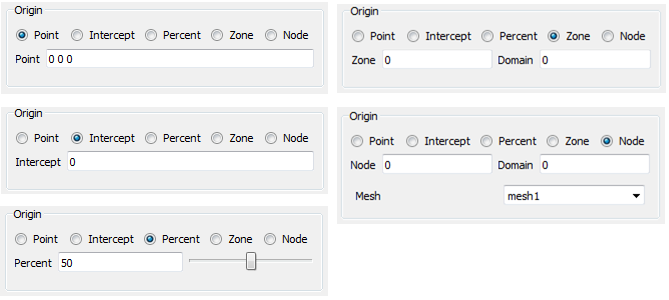
Fig. 4.58 Origin area appearance
If you don’t know a good value to use for the intercept, consider using the percent slice mode. Percent slice mode, which is most often used for an orthogonal slice, allows you to slice along a particular axis using some percentage of the distance along that axis. For example, this allows you to see what the slice plane looks like if its origin is 50% of the distance along the X-Axis. To set the origin using a percentage of the distance along an axis, click the Percent radio button and then type a new percentage value into the Percent text field or use the Percent slider.
Sometimes it is useful to slice through a particular zone or node. The Slice operator allows you to pick an origin for the slice plane so a specific zone or node lies in the slice plane. To make sure that a particular zone is sliced by the Slice operator, click on the Zone radio button and then enter the zone to be sliced into the Zone text field. Be sure to also enter the domain that contains the zone into the Domain text field if you are slicing a multi-domain database. If you want to make sure that the slice plane’s origin is at a specific node in a mesh, click the Node radio button and enter a new node number into the Node text field. Note that you must also specify a domain if you are slicing a multi-domain database. If the database contains multiple meshes, their will also be Mesh combo box option from which to choose the mesh to use, as seen in the Node example in Figure 4.58.
Use the up-axis vector when you want the slice plane to be projected to 2D. The up-axis vector is a vector that lies in the slice plane and defines a 2D coordinate system within the plane where the up-axis vector corresponds to the Y-axis. To change the up-axis vector, type a new 3D vector into the Direction text field in the Up Axis area of the window.
4.3.24.2. Positioning the slice plane using the Plane Tool
You can also position the slice plane using VisIt’s interactive plane tool. The plane tool, which is available in the visualization window’s popup menu, allows you to position a slice plane interactively using the mouse. The plane tool is an object in the visualization window that can be moved and rotated. When the plane tool is changed, it gives its new slice plane to the Slice operator if the operator is set to accept information interactively. To make sure that the Slice operator can accept a new slice plane from the plane tool, check the Interactive check box in the Slice attributes window. For more information about the plane tool, read the Interactive Tools chapter.
4.3.24.3. Projecting the slice to 2D
The Slice operator usually leaves sliced plots in 3D so you can position the slice with the plane tool. However, you might want the plot projected to 2D. When a sliced plot is projected to 2D, any 2D operation, like Lineout , can be applied to the plot. To project a plot to 2D, check the Project 2D check box in the Slice attributes window .