12. Partitioning
This tutorial describes how to Partition meshes.
12.1. Partitioning overview
Partitioning meshes is commonly needed in order to evenly distribute work among many simulation ranks. VisIt provides the ability to partition meshes when exporting data in Blueprint format. Full M to N repartioning is supported for both structured and unstructured meshes.
The partitioning algorithms built into VisIt are fairly simple. The goal was not to provide sophisticated partiting algorithms but rather provide the mechanism to partition the data. In order to support more sophisticated partitioning algorithms, VisIt supports the ability to use a variable to specify the partitioning. This enables using an external repartitioning tool to define the partitions.
12.2. The built-in partitioning algorithm
12.2.1. Increasing the number of blocks
The built-in partitioning algorithm will split blocks when increasing the number of blocks. It will first sort the list of blocks from largest to smallest in terms of cell count. It will then split the largest block and insert the two new blocks into the list in the appropriate locations. It will continue splitting the largest block and inserting the new blocks into the list until the desired number of blocks is reached. In the case of an unstructured mesh it will split the block in half. In the case of a structured mesh it will split it in half along the longest dimension based on the number of cells.
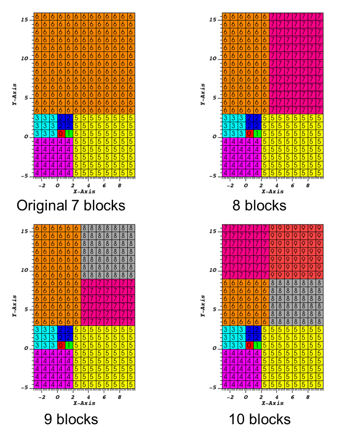
Fig. 12.21 Examples of increasing the number of blocks
12.2.2. Decreasing the number of blocks
The built-in partitioning algorithm will merge blocks when decreasing the number of blocks. It will first sort the list of blocks from largest to smallest in terms of cell count. It will then merge the two smallest blocks and insert the block into the list in the appropriate location. It will continue merging the two smallest blocks and inserting the new block into the list until the desired number of blocks is reached. In the case of an unstructured mesh it will merge matching points. By default, the points must match exactly to be merged. It is possible to set a merge tolerance that indicates how close two points need to be to be considered a match. In the case of a structured mesh it will try to maintain it as a structured mesh if possible. If it is not possible, it will convert them to an unstructured mesh and merge matching points as specified above.
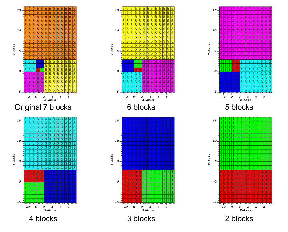
Fig. 12.22 Examples of decreasing the number of blocks
12.3. An example of using the built-in partitioning algorithm
Here we will go through an example of partitioning a 3-dimensional multi-block unstructured mesh.
Let us start by opening a file and creating a plot.
Open the file
multi_ucd3d.silo.Create a Subset plot of
domains(mesh1).
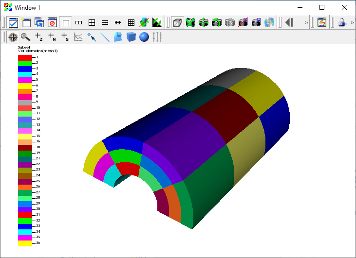
Fig. 12.23 Subset plot of the original 36 block mesh
Now we are ready to export the data.
Go to File->Export database.
This brings up the Export Database window.
Change the File name to
multi_ucd_repart.Change the Export to to Blueprint.
Click Apply and Export.
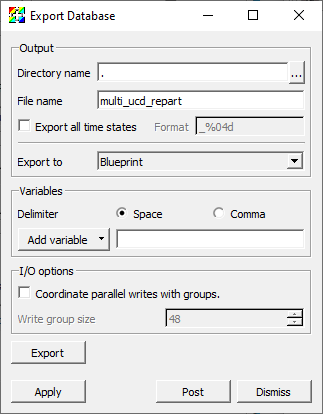
Fig. 12.24 The Export Database window.
This will bring up the Export options for Blueprint writer window.
Change the Operation to Partition.
Change the Partition target number of domains to
2.Click OK.
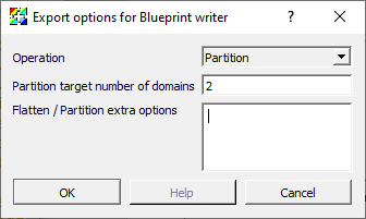
Fig. 12.25 The Blueprint writer window
Now let us plot the new partitioned mesh.
Click Delete in the main control window.
Open the file
multi_ucd3d_repart.cycle_000000.root.Create a Subset plot of
domains.
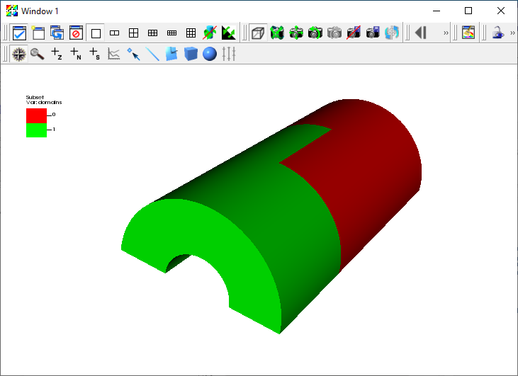
Fig. 12.26 Subset plot of the new partitioned 2 block mesh
12.4. An example of using a field to partition the mesh
Here we will go through an example of partitioning a 3-dimensional rectilinear mesh using a field. The field will be generated using a expression that has ones and zeros to partition the mesh into two arbitrary blocks.
Let us start by opening a file and creating a plot.
Open the file
noise.silo.Create a Pseudocolor plot of
hardyglobal.
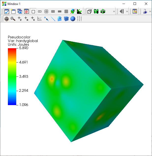
Fig. 12.27 Pseudocolor plot of hardyglobal
We will use the hardyglobal variable to create a variable that is one where the variable is greater than or equal to 2.8 and zero otherwise.
Go to Controls->Expressions.
Click New to create a new expression.
Change the Name text field to
part.Set the Definition to
if(ge(recenter(hardyglobal),zonal_constant(Mesh, 2.8)),zonal_constant(Mesh,1.),zonal_constant(Mesh,0.))
Click Apply and Dismiss.
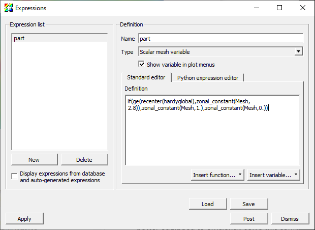
Fig. 12.28 Defining part in the Expressions window
Now let us look at the part variable.
Go to Variables->part to change the Pseudocolor variable to
part.
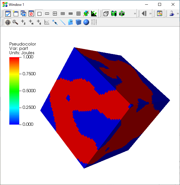
Fig. 12.29 Pseudocolor plot of part
Now we are ready to export the data. When partitioning using a variable the partitioning variable must either be the variable being plotted or listed as one of the variables in the Variables portion of the window. In this case we are plotting the partitioning variable, so we do not have to list it as an additional variable.
Go to File->Export database.
This brings up the Export Database window.
Change the File name to
noise_repart.Change the Export to to Blueprint.
Click Apply and Export.
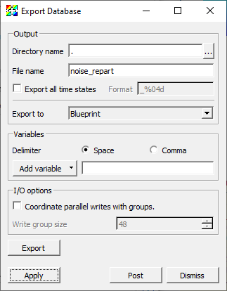
Fig. 12.30 The Export Database window.
This will bring up the Export options for Blueprint writer window.
Change the Operation to Partition.
Change the Partition target number of domains to
2.Change the Flatten/Partition extra options to
selections:
  -
   type: field
   domain_id: any
   field: part
Note that the options are in yaml and the indentation is critical.
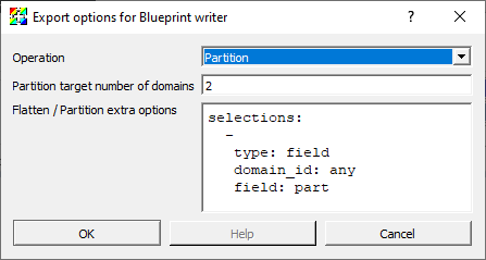
Fig. 12.31 The Blueprint writer window
Now let us plot the new partitioned mesh.
Click Delete in the main control window.
Open the file
noise_repart.cycle_000000.root.Create a Subset plot of
domains.
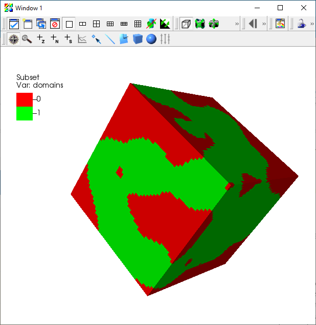
Fig. 12.32 Subset plot of the new partitioned 2 block mesh