4.3.34. Transform operator
The Transform operator manipulates a 2D or 3D database’s coordinate field by applying rotation, scaling, and translation transformations. The operator’s transformations are applied in the following order: rotation, scaling, translation. The Transform operator is applied to databases before they are plotted. You might use the Transform operator to rotate database geometry to a more convenient orientation or to scale database geometry to make better use of the visualization window. You can also use the Transform operator to make objects rotate and move around the visualization window during animations. This works well when only one part of the visualization should move while other parts and the view remain fixed. An example of the Transform operator is shown in Figure 4.82.
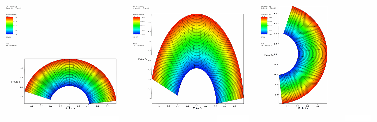
Fig. 4.82 Transform operator example
4.3.34.1. Rotation
You can use the Transform operator to rotate plots around an arbitrary axis in 3D and around the Z-axis in 2D. To apply the rotation component of the Transform operator, be sure to check the Rotate check box in the Transform attributes window (Figure 4.83). An origin and normal are needed to specify the axis of rotation. The origin serves as a reference point for the object being rotated. The axis of rotation is a 3D vector that, along with the origin, determines the 3D axis that will serve as the axis of rotation. You must supply an origin and an axis vector to specify an axis of rotation. To change the origin, type a new 3D vector into the top Origin text field. To change the 3D axis, type a new 3D vector into the Axis text field. Both the origin and the axis are represented by three space-separated floating point numbers.
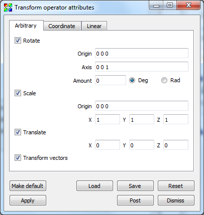
Fig. 4.83 Transform attributes window
When applying the Transform operator to plots, you probably want to make the origin the same as the center of the plot extents which can be found by looking at the axis annotations. When the Transform operator is applied to 3D plots, the axis of rotation can be set to any unit vector. When the Transform operator is applied to 2D plots, the axis of rotation should always be set to the Z-axis (0 0 1).
Once you specify the axis of rotation, you must supply the angle of rotation. The default angle of rotation is zero degrees, which gives no rotation. To change the angle of rotation, enter a number in degrees or radians into the Amount text field and click the Deg radio button for degrees or the Rad radio button if the angle is measured in radians.
4.3.34.2. Scale
You can use the Transform operator to scale plots. Each dimension can be scaled independently by entering a new scale factor into the X, Y, Z text fields. Each scale factor is a multiplier so that a value of 1 scales plots to their original size while a value of 2 scales plots to twice their original size. To apply the scale component of the Transform operator, be sure to check the Scale check box in the Transform attributes window . All dimensions are scaled relative to a scaling origin which can be changed by typing a new origin into the middle lower Origin text field.
4.3.34.3. Translation
You can use the Transform operator to translate plots. To apply the translation component of the Transform operator, be sure to check the Translate check box in the Transform attributes window . To translate plots in the X dimension, replace the default value of zero in the X translation text field. Translations in the Y and Z dimensions are handled in the same manner.
4.3.34.4. Coordinate system conversion
In addition to being able to rotate, scale, and translate plots, the Transform operator can also perform coordinate system conversions. A plot’s coordinates can be specified in terms of Cartesian, Cylindrical, or Spherical coordinates (illustrated in Figure 4.84). Ultimately, when a plot is rendered in the visualization window, its coordinates must be specified in terms of Cartesian coordinates due to the implementation of graphics hardware. If you have a database where the coordinates are not specified in terms of Cartesian coordinates, you can apply the Transform operator to perform a coordinate system transformation so the plot is rendered correctly in the visualization window.
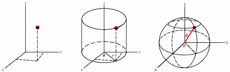
Fig. 4.84 Cartesian, Cylindrical, Spherical coordinate systems
Figure 4.85 shows a model of an airplane that is specified in terms of spherical coordinates. When it is rendered initially, VisIt assumes that the coordinates are Cartesian, which leads to the plot getting stretched and tangled. The Transform operator was then applied to convert the plot’s spherical coordinates into Cartesian coordinates, which allows VisIt to draw the plot as it is intended to look.
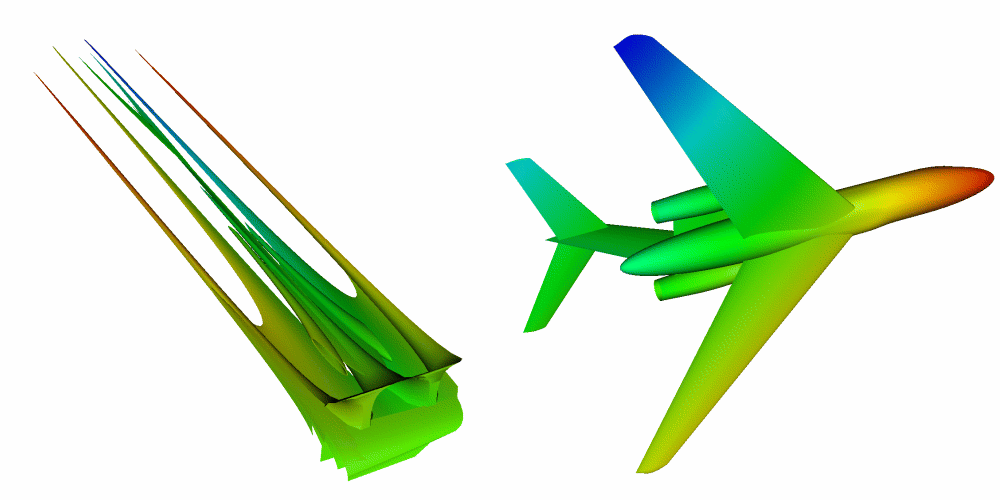
Fig. 4.85 Coordinate system conversion using the Transform operator
The Transform operator allows coordinate system transformations between any of the three supported coordinate systems, shown in Figure 4.86 . To pick a coordinate system transformation, you must first pick the coordinate system used for the input geometry. Next, you must pick the desired output coordinate system. In the example shown in Figure 4.85, the input coordinate system was Spherical and the output coordinate system was Cartesian. Note that if you use the Transform operator to perform a coordinate system transformation then you cannot also perform rotation, scaling, or translation. If you must perform any of those operations, add a second Transform operator to your plots.
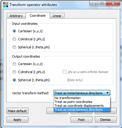
Fig. 4.86 Supported coordinate systems
4.3.34.5. Linear (Affine) transforms
Linear, or Affine, transforms can be specified via a 4x4 matrix as shown in Figure 4.87. This represents a class of operations often used for coordinate system transformations known as spatial transformation matrices. Why is the matrix 4x4 instead of 3x3? Typically, the 4th row of the matrix is left unchanged but the 4th column permits the inclusion of translation in the same linear matrix operator used to support other things like rotation and scaling.
Vectors will be transformed by default, uncheck the transform vectors checkbox if this is not desired. The inverse transform can be applied by selecting Invert linear transform.
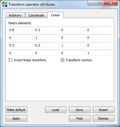
Fig. 4.87 Linear transformation options
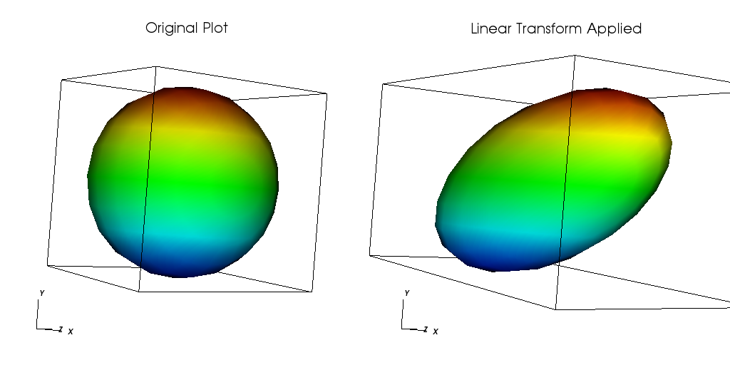
Fig. 4.88 Linear transformation example