4.3.14.4. Poincaré operator
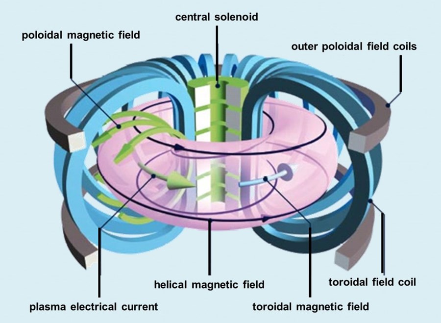
The Poincaré operator constructs a Poincaré section for toroidal geometry. The basis of constructing a connected plot is to accurately determine the number of toroidal and poloidal windings (i.e. the winding pair). The image below is helpful for visually understanding what is meant by toroidal and poloidal:
This process is iterative, starting with a minimum number of puncture points through a Poincaré section and continuing until the toroidal and poloidal windings are known or the maximum number of punctures is reached. If an accurate winding pair is determined, then the puncture points are connected based on it. For more information, refer to the following resources:
4.3.14.4.1. Source
The set of points that seed the integral curves that reveal the Poincaré section. In addition to the Source attributes common to all ICS operators, the Poincaré operator supports the following attributes:
4.3.14.4.1.1. Source Type
The source type controls how the seeds for curves are created. There are various options, the names of which are self-descriptive such as creating them along a line. Only those options that require further clarification are described further here.
- Point List
Seed from a list of points. In addition to Add Point, Delete Point, and Delete All Points, the user can Read Text File that is formatted with one point per each line either as “X Y Z” or “X, Y, Z”.
Warning
If the Field is set to M3D-C1 integrator the point locations will be converted from Cartesian to Cylindrical coordinates. In the 2D case, phi will be set to 0.
4.3.14.4.2. Integration
Specify settings for numerical integrators. In addition to the Integration attributes common to all ICS operators, the Poincaré operator supports the following attributes.
4.3.14.4.2.1. Punctures
While integrating the integral curve to be used the for Poincaré plot, the user has the option to require a minimum number of initial punctures through the Poincaré section for the analysis. The user may limit the integration in case of run-a-way integral curve that cannot be fully analyzed.
- Puncture plot type
The type of the puncture plot. Options are:
Single - the analysis is based on the standard double periodic system (toroidal-poloidal periodicity)
Double - the analysis is based on the double Poincaré plot. In addition to the toroidal-poloidal periodicity a third periodicity exists that is based on the integration time.
When selecting double, Poincaré plot puncture points are accepted if and only if the period is within the tolerance of the period (the period is set as part of the Poincaré Pathline Options).
Period tolerance - when an integral curve punctures the plane, the period must be within the tolerance value.
Warning
When selecting “Toroidal” the “Analysis” must also be set to “Punctures only” as there is currently no analysis in the toroidal plane.
4.3.14.4.3. Analysis
The user may adjust settings for how Poincaré analysis is to be done. Some options include:
- None - Puncture only
This will result in constructing a traditional Poincaré plot using only points.
- Full
This will analyze each curves’ geometry and attempt to reconstruct the cross sectional profile of the surface which the curve lies on. Further, the analysis attempts to identify the topology of the surface.
- Maximum toroidal winding
Limit the search of the toroidal winding to lower order values. Zero indicates no limit.
- Override toroidal winding
In some cases, such as debugging, it may be informative to force the toroidal winding to have a set value. Zero indicates no override.
- Override poloidal winding
In some cases such as debugging, it may be informative to force the poloidal winding to have set value. Zero indicates no override.
- Winding pair confidence (Range 0-1, Default 0.9)
Sets the limit for the number of mismatches in the consistency in the winding pairs.
- Detect Rational Surface
Allows for the construction of rational surfaces via an iterative process. Typically, they can be constructed with 5-10 iterations.
Danger
The rational surface construction is experimental code and does not always work.
- Detect O Points
Allows for the detection of O points in “island chains” via an iterative process. Typically, they can be detected with 5 iterations.
Danger
The critical point detection is experimental code and does not always work.
- Perform O-Line Analysis
Calculate the poloidal winding relative the O-Line (central axis) which provides a more accurate winding value.
O-Line toroidal windings (Default 1) – sets the toroidal winding value, i.e. the period (for the central axis the period is 1).
O-Line Axis Point File - allows the user to select a text file containing the points along the axis from 0 to 360 degrees (note there is no overlap P(0) != P(n)).
- Show chaotic fieldlines as points
Because chaotic curves cannot be classified, they are not displayed unless this is checked.
- Show islands only
Culls the results so that only island chains are displayed.
- Show ridgelines
Displays the 1D plots of the distance and ridgeline samples.
- Verbose
Dumps information regarding the analysis to the terminal. The final summary may be useful. For example,
Surface id = 0 < 2.35019 0 0.664124 > 121:11 121:11 (11) flux surface with 4 nodes (Complete)
Surface id = 0
seed location < 2.35019 0 0.664124 >
the winding pair 121:11
the toroidal:poloidal periods (as a winding pair) 121:11
the multiplication faction (11) i.e. diving by this number will give the base winding values, in this case 11:1.
surface type: flux surface
number of nodes in each winding group: with 4 nodes
analysis state: complete.
4.3.14.4.4. Appearance
The appearance tab specifies how the integral curve will be rendered. In addition to the Appearance attributes common to all ICS operators, the Poincaré operator supports the following attributes.
4.3.14.4.4.1. Coloring
The various coloring options are:
- None
Solid color from the single color
- Safety Factor Q
Use the safety factor
- Safety Factor P
Use the safety factor as defined when there are two possible choices for the magnetic axis
- Safety Factor Q == P
Render the surfaces on if the safety factor Q is equal to the safety factor P
- Safety Factor Q != P
Render the surfaces on if the safety factor Q is not equal to the safety factor P
- Toroidal Windings Q
Use the toroidal winding value used in the calculation of Q
- Toroidal Windings P
Use the toroidal winding value used in the calculation of P
- Poloidal Windings
Use the poloidal winding value
- Fieldline Order
Use input order of the seeds used to generate the integral curves.
- Point Order
Use the puncture point index
- Plane
Use the plane value (integer from 0 to N where N is the number of planes)
- Winding Group Order
Use the winding group order (integer from 0 to T where T is the toroidal winding)
- Winding Point Order
Use the index of the puncture points within each winding group
- Winding Point Order Modulo Order
Use the order of the punctures within each winding group modulo the toroidal windings (useful for islands in islands)
4.3.14.4.4.2. Display
Allows the users to display the results in a single plane or multiple planes. Further, one can reconstruct the 3D surface that the curves lies on.
4.3.14.4.4.3. Overlapping Curve Sections
When displaying the data in a connected manner the raw data will often overlap itself. As such, for visually pleasing results it may be preferable to remove the overlaps.
- Raw
Display all of the punctures points in a connected fashion.
- Remove
Display all of the punctures points in a connected fashion, removing the overlapping sections.
- Merge
Display all of the punctures points in a connected fashion, merging the overlapping sections. Experimental.
- Smooth
Display all of the punctures points in a connected fashion, removing the overlapping sections while smoothing between points.
Danger
Smooth is experimental and does not always work.